PDCCH method in enhanced CA and apparatus thereof

A current configuration and service cell technology, applied in the field of CA scheduling, can solve problems such as the increase of the total number of DCI bits, multiple air interface resources, and the degradation of DCI reception performance, and achieve the effect of increasing degrees of freedom and decoupling

Active Publication Date: 2016-10-05
SHANGHAI LANGBO COMM TECH CO LTD
View PDF2 Cites 2 Cited by
  • Summary
  • Abstract
  • Description
  • Claims
  • Application Information

AI Technical Summary

Problems solved by technology

Among the above methods, the former leads to an increase in the total number of DCI bits, which in turn causes DCI to occupy

Method used


Image

  • PDCCH method in enhanced CA and apparatus thereof
  • PDCCH method in enhanced CA and apparatus thereof
  • PDCCH method in enhanced CA and apparatus thereof

Examples


Embodiment 1

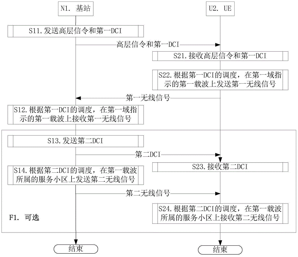
[0085] Embodiment 1 illustrates the flow chart of wireless signal transmission, as attached figure 1 shown. attached figure 1 In , the base station N1 maintains the serving cell of the UE U2, the steps in block F1 are optional.

[0086] For the base station N1, in step S11, high-layer signaling and a first DCI are sent, the high-layer signaling indicates cell indexes of K serving cells, and the first DCI includes a first field. In step S12, according to the scheduling of the first DCI, the first wireless signal is received on the first carrier indicated by the first field. In step S13, the second DCI is sent. In step S14, according to the scheduling of the second DCI, the second radio signal is sent on the serving cell to which the first carrier belongs.

[0087] For UE U2, in step S21, high layer signaling and first DCI are received. In step S22, according to the scheduling of the first DCI, the first wireless signal is sent on the first carrier indicated by the first fiel...

Embodiment 2

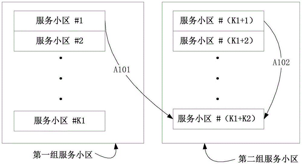
[0096] Embodiment 2 illustrates a schematic diagram of a transmission carrier for scheduling signaling, as shown in the attached figure 2 shown.

[0097] The base station first sends high-level signaling and the first DCI to the target UE, the high-level signaling indicates cell indexes of (K1+K2) serving cells, and the first DCI includes the first field. The base station then receives the first radio signal sent by the target UE on the first carrier indicated by the first field according to the scheduling of the first DCI. The base station then sends the third DCI to the target UE. Finally, the base station receives the third radio signal sent by the target UE on the first carrier indicated by the first field according to the scheduling of the third DCI.

[0098] In Embodiment 2, the first carrier is jointly indicated by the first field and the scheduling direction (ie, uplink) of the first DCI. Said K is a positive integer. The target UE is currently configured with (K1...

Embodiment 3

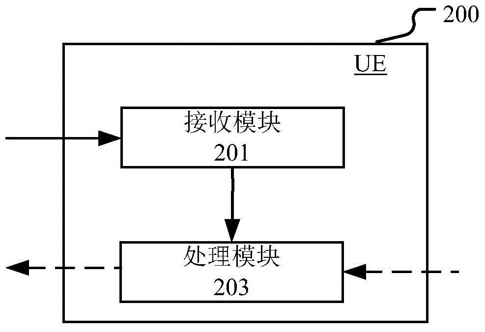
[0102] Embodiment 3 illustrates a structural block diagram of a processing device used in a UE, as shown in the attached image 3 shown. attached image 3 Among them, the UE processing device 200 is composed of a receiving module 201 and a processing module 202.

[0103] The receiving module 201 is configured to receive high-level signaling and a first DCI, the high-level signaling indicates cell indexes of K serving cells, and the first DCI includes a first field. The processing module 202 is configured to process the first wireless signal on the first carrier indicated by the first field according to the scheduling of the first DCI.

[0104] In Embodiment 3, the first carrier is jointly indicated by the first field and the scheduling direction of the first DCI, the scheduling direction is uplink and the processing is sending, or the scheduling direction is downlink and the processing is receiving. The first carrier is a carrier of one of the K serving cells, where K is a ...


PUM


Abstract

The invention provides a scheduling method and an apparatus in enhanced carrier wave aggregation. In a first step, UE receives a high level signaling and a first DCI, wherein the high level signaling indicates cell indexes of K service cells and the first DCI includes a first domain. In a second step, according to scheduling of the first DCI, a first wireless signal is processed on a first carrier wave indicated in the first domain. The first carrier wave is indicated by the first domain and a scheduling direction of the first DCI. The scheduling direction is an uplink and the processing is sending, or the scheduling direction is a downlink and the processing is receiving. The first carrier wave is the carrier wave of one service cell of the K service cells and the K is a positive integer. In the invention, a ''coupling'' relation of uplink and downlink scheduling is removed and scheduling flexibility is increased. In addition, a load size of a control signaling is not increased.

Description

technical field [0001] The present invention relates to a CA (Carrier Aggregation, carrier aggregation) scheduling scheme, in particular to a CA scheduling scheme based on an LTE (Long Term Evolution, long-term evolution) system. Background technique [0002] In the LTE system R (Release, version) 10 formulated by the traditional 3GPP (3rd Generation Partner Project, the third generation partnership project), CA is introduced as one of the key technologies, and its core idea is UE-User Equipment Able to work on multiple carriers simultaneously, CA can increase the peak rate of a single UE. In LTE CA, a UE is configured with one Pcell (Primary Cell, primary serving cell) and one or more Scells (Secondary Cell, secondary serving cell). For FDD (Frequency Duplex Division, Frequency Division Duplex) LTE, one serving cell includes at least one downlink carrier in {one downlink carrier, one uplink carrier}. For TDD (Time Duplex Division, Time Division Duplex) LTE, one serving ce...

Claims


Application Information

Patent Timeline
IPC IPC(8): H04L5/00H04W72/12
Inventor 张晓博
Owner SHANGHAI LANGBO COMM TECH CO LTD
Why Eureka
Try Eureka