Multi-pipe discharging device of sinter shaft kiln type waste heat recovery system

A waste heat recovery system and sintering ore technology are applied in the direction of furnace control devices, processing discharged materials, vertical furnaces, etc., which can solve problems such as insufficient cooling, discharge of red materials, and fast discharge of materials, and achieve the goal of eliminating red material accidents Effect

Active Publication Date: 2016-11-16
江苏垦乐节能环保科技有限公司
View PDF5 Cites 15 Cited by
  • Summary
  • Abstract
  • Description
  • Claims
  • Application Information

AI Technical Summary

Problems solved by technology

As a result, the sintered ore is discharged quickly in a local area, the cooling is not sufficient, and the phenomenon of red material discharge occurs
In the shaft kiln cooling device for sinter, it is obviously impossible to solve the "central funnel effect" caused by sinter segregation by using one discharge port and setting the adjustment rod at the lower part of the discharge cone. An effective method must be found to solve the problem. Method of local material segregation and red material discharge

Method used


Image

  • Multi-pipe discharging device of sinter shaft kiln type waste heat recovery system
  • Multi-pipe discharging device of sinter shaft kiln type waste heat recovery system

Examples


Embodiment Construction

[0013] The present invention will be further described in detail below in conjunction with the accompanying drawings and embodiments.

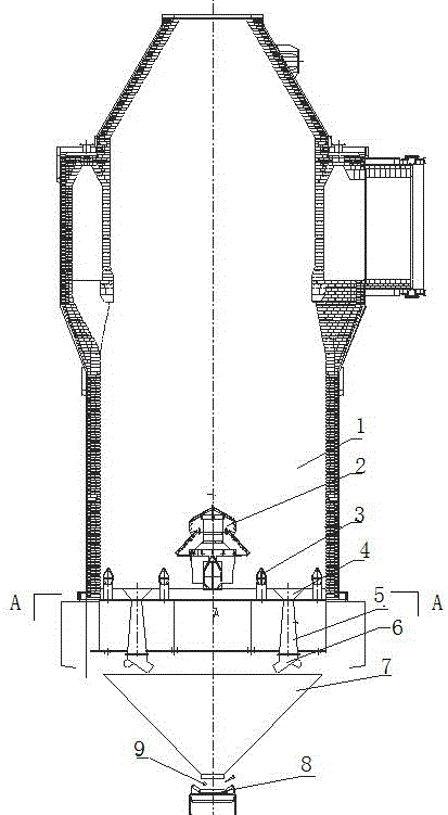
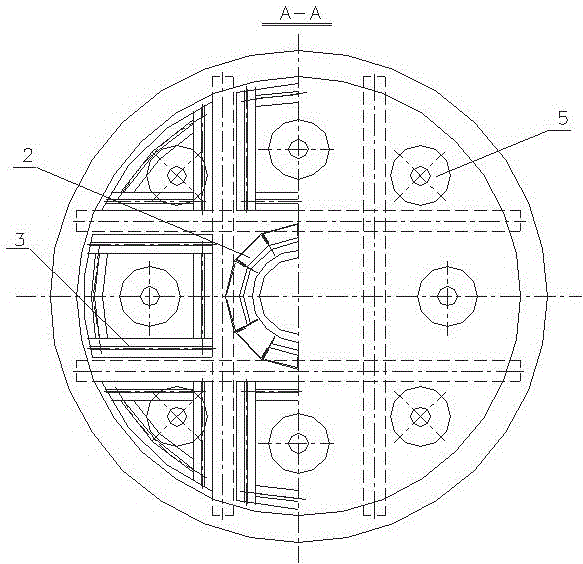
[0014] see figure 1 , as shown in 2, a multi-tube discharge device of a sinter shaft kiln waste heat recovery system in this embodiment includes a central air inlet pipe 2 arranged at the bottom of the cooling section of the kiln body 1, and the central air inlet pipe 2 There are multiple peripheral air inlet pipes 3 evenly arranged on both sides of the kiln body. The peripheral air inlet pipes 3 are arranged in a radial or "well" shape at the bottom of the kiln body. Each peripheral air inlet pipe 3 is independently adjusted according to the discharge temperature to reach the kiln body. The sinter temperature, air temperature, and airflow distribution on the same section tend to be consistent, and the sinter on the same section is also in a balanced state of feeding. The central air inlet pipe 2 and a plurality of peripheral air inlet pipes ...


PUM


Abstract

The invention relates to a multi-pipe discharging device of a sinter shaft kiln type waste heat recovery system and relates to flow characteristics of sinter, heat exchange characteristics of the sinter and air, out-of-kiln manners of hot air, structural forms of kiln bodies, diameter and height parameters, kiln top material distributing equipment, bottom air distribution devices and the like. A multi-pipe type discharging technology is adopted and matched with air volume adjustment, a kiln wall effect and a center funnel effect are avoided, and the inherent defect that the adjusting range of an adjusting bar manner is very limited is effectively overcome. Due to the efficient cooperation of the discharging technology and the air distribution manner, the comprehensive effects of increasing the air temperature, reducing the air volume and the air resistance and eradicating red material accidents can be achieved.

Description

technical field [0001] The invention relates to a sinter shaft kiln waste heat recovery system, in particular to a multi-pipe discharge device of the sinter shaft kiln waste heat recovery system. Background technique [0002] The sinter is cooled by shaft kiln, which is a technical transplantation of CDQ, and the particle size range of CDQ coke is small and the powder is less (about 8% for <25mm, 60-70% for 25-60mm, and about 60% for >80mm 8%), segregation is not easy to occur, and the only funnel-type discharge is adopted, and adjusted with the adjustment rod, which can effectively solve the problem of partial temperature of coke and discharge of red material. According to the manual of the sintering machine, the sinter cake turned down by the sintering machine is broken to less than 150mm and then enters the cooling equipment, and the sintered ore content of 5-0mm particle size is as high as 18-20%. Due to the large size difference, the large proportion of powder ma...

Claims


Application Information

Patent Timeline
Patent Type & Authority Applications(China)
IPC IPC(8): F27B1/21F27B1/24F27B1/26F27D15/02F27D17/00F27D19/00
CPCF27B1/21F27B1/24F27B1/26F27D15/02F27D17/004F27D19/00F27D2019/0003F27D2019/0043F27D2019/0056Y02P10/25
Inventor 赵海浩郝丙星缪胜东李娟孙大伟张成权
Owner 江苏垦乐节能环保科技有限公司
Why Eureka
Try Eureka