Intermediate-depth part geothermal energy heating system

A technology of heating system and geothermal energy, which is applied in the direction of hot water central heating system, geothermal energy, heating system, etc. It can solve the problems of long-term operation performance degradation of the system, easy to be restricted by site conditions, and large area of ​​buried pipes. To achieve the effects of abundant reserves, great potential for development, and improved utilization

Inactive Publication Date: 2016-12-07
XI AN JIAOTONG UNIV
View PDF7 Cites 4 Cited by
  • Summary
  • Abstract
  • Description
  • Claims
  • Application Information

AI Technical Summary

Problems solved by technology

However, the following problems occurred during the application process: (1) Cold and heat imbalance. The ground source heat pump mainly uses the heat storage effect of shallow rock and soil. If there is an imbalance between cold and heat during winter and summer operation, the long-term operation performance of the system will decline. ;(2) The buried pipes of the buried pipe ground source heat pump system occupy a large area. Especially in the process of urban development in my country, land resources are increasingly scarce and the volume ratio is high. The buried pipe ground source heat pump system is easily restricted by site conditions; (3) Ground water source heat pump is also a type of ground source heat pump. It is generally an energy-saving and environmentally friendly technology that uses shallow groundwater with stable temperature as the medium and realizes heat exchange through the water circulation of pumping wells and recharge wells.
However, the actual promotion and application of the groundwater source heat pump system still faces a series of underground engineering problems such as the protection of groundwater resources, thermal short circuit, deformation of rock and soil layers, and cold and heat island effect.

Method used


Image

  • Intermediate-depth part geothermal energy heating system
  • Intermediate-depth part geothermal energy heating system
  • Intermediate-depth part geothermal energy heating system

Examples


Embodiment Construction

[0013] The present invention will be described in further detail below in conjunction with the accompanying drawings.

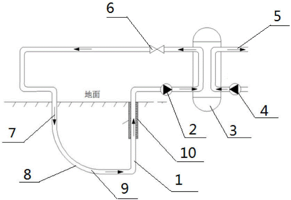
[0014] see figure 1 , the present invention includes a vertical well 1 extending vertically to 2000m underground and a docking well 7 connected with the vertical well 1 at the same depth, and an arc-shaped deflection section is set after the docking well 7 goes vertically down to 1700m 8 is connected to the vertical well 1 at a depth of 2000m underground, and a casing 9 with an inner diameter of 150mm is laid in the vertical well 1 and the docking well 7 to communicate with each other. The surface of the surface is covered with a polyurethane rigid foam insulation material layer 10 with a thickness of 20mm. The casing 9 at the outlet of the vertical well 1 is connected to the heat-absorbing side of the ground-source heat pump 3 through the water pump 2 on the heat-absorbing side. The heat-absorbing side outlet of the heat pump 3 communicates with the casing ...


PUM


Abstract

An intermediate-depth part geothermal energy heating system comprises a vertical well vertically extending to the underground part by 2,000 m, and a butt joint well communicating with the vertical well, wherein the vertical well and the butt joint well are the same in depth. After the butt joint well is vertically downwards dug by 1,700 m, an arc deflection section is arranged to be connected with the part, at the underground position of 2,000 m, of the vertical well. Communicating casing pipes are laid in the vertical well and the butt joint well. The casing pipe at an outlet of the vertical well is connected with the heat absorbing side of a ground source heat pump through a water pump. An outlet in the heat absorbing side of the ground source heat pump communicates with the casing pipe in the butt joint well to form a closed circulation loop, and the heat exchange side of the ground source heat pump is connected with a tail end user. The vertical depth of the casing pipes is increased to 2,000 m from the conventional depth of 100 m, the vertical well and the butt joint well are effectively connected in the deep soil, a horizontal heat exchange pipeline is established at the underground position of 2,000 m, a closed circulation system is adopted, softened fresh water efficiently exchanges heat with deep rock soil, and the deep geothermal energy is extracted to be used for building heat supply.

Description

technical field [0001] The invention relates to a geothermal energy heating system, in particular to a mid-deep geothermal energy heating system capable of efficiently extracting mid-deep geothermal energy for building heating. Background technique [0002] Ground source heat pump technology makes good use of the heat storage effect of underground shallow rock and soil, and has a remarkable energy-saving effect. It has been developed rapidly in recent years. However, the following problems occurred during the application process: (1) Cold and heat imbalance. The ground source heat pump mainly uses the heat storage effect of shallow rock and soil. If there is an imbalance between cold and heat during winter and summer operation, the long-term operation performance of the system will decline. ;(2) The buried pipes of the buried pipe ground source heat pump system occupy a large area. Especially in the process of urban development in my country, land resources are increasingly s...

Claims


Application Information

Patent Timeline
Patent Type & Authority Applications(China)
IPC IPC(8): F24D3/18F24J3/08
CPCF24D3/18F24T10/10F24D2200/11Y02B10/40Y02E10/10
Inventor 王沣浩田春
Owner XI AN JIAOTONG UNIV
Why Eureka
Try Eureka