Terminal compensation control method for intermediate frequency power supply system

A technology of power supply system and compensation control, applied in the direction of AC network voltage adjustment, etc., can solve problems such as voltage fluctuations, achieve the effects of solving voltage fluctuations, improving dynamic compensation capabilities, and solving instantaneous voltage drops

Active Publication Date: 2016-12-21
NAVAL UNIV OF ENG PLA
View PDF2 Cites 2 Cited by
  • Summary
  • Abstract
  • Description
  • Claims
  • Application Information

AI Technical Summary

Problems solved by technology

[0011] The purpose of the present invention is to provide a terminal compensation control method for an intermediate frequency power supply system, which can simultaneously solve the problem of steady-state line voltage drop in the intermediate frequency power supply system, voltage fluctuations caused by load switching, instantaneous voltage drops, phase compensation, etc. Quality problems, to ensure the reliable and stable operation of each load in the system

Method used


Image

  • Terminal compensation control method for intermediate frequency power supply system
  • Terminal compensation control method for intermediate frequency power supply system
  • Terminal compensation control method for intermediate frequency power supply system

Examples


Embodiment Construction

[0023] The present invention will be further described in detail below in conjunction with the drawings and specific embodiments:

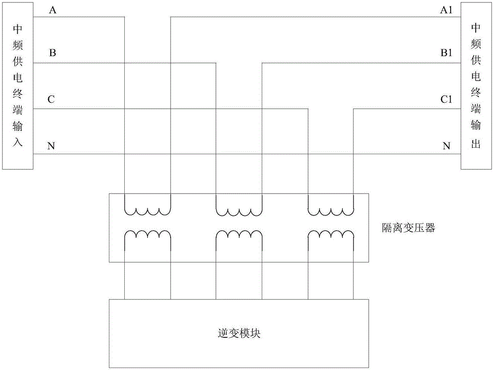
[0024] Such as figure 2 Shown is the block diagram of the terminal compensation principle of the intermediate frequency power supply system.

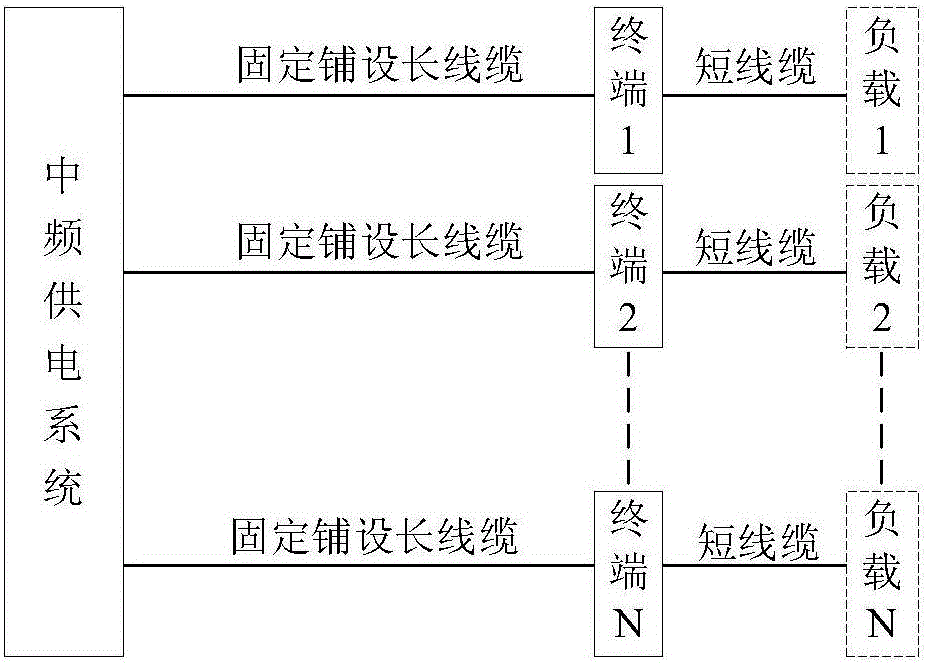
[0025] Take a terminal output of an intermediate frequency power supply system as an example: the terminal input and output power systems of the intermediate frequency power supply system are all three-phase four-wire systems, and the terminal three-phase input phase voltages are U AN , U BN And U CN , The terminal three-phase output phase voltage is U A1N , U B1N And U C1N , The secondary of the terminal compensation isolation transformer is connected in series between the three-phase input and output phase voltages. IF power supply system figure 1 The shown fixedly laid long cables are connected to the terminal, and when the terminal is running under load, the steady-state voltage drop of the long cable...


PUM


Abstract

The invention relates to a terminal compensation control method for an intermediate frequency power supply system. A phase-locked loop is adopted for tracking a terminal input voltage phase position of the intermediate frequency power supply system, the phase position is subjected to phase shift operation and feedforward compensation operation based on an output current and a wire cable phase shift coefficient, and a terminal output voltage reference phase position is obtained; based on the terminal output voltage reference phase position, terminal output voltage can be dynamically compensated in a real time manner via staggering of switching frequencies and adjustment of alternating current quantity proportional resonance under a stationary coordinate system. Terminal compensation control in the terminal compensation control method for the intermediate frequency power supply system is dual compensation for an output voltage amplitude and phase position; line inductive reactance between terminal output and a load is taken into consideration, feedforward compensation of a reference voltage phase position is added, a problem of voltage fluctuation caused via load switching operation is solved, compensation voltage is subjected to under alternating current quantity proportional resonance adjustment under the stationary coordinate system, terminal dynamic compensation capability is improved, and a problem of an instantaneous voltage decline can be solved.

Description

Technical field [0001] The invention relates to the technical field of inverter compensation control, in particular to a terminal compensation control method for an intermediate frequency power supply system. Background technique [0002] With the development of the IF centralized power supply system, the issue of the output power quality of the IF power supply system has received increasing attention. figure 1 In the centralized power supply mode shown, the different loads in the system are all concentrated in an intermediate frequency grid, and their working conditions may be coupled to each other, and different loads will also have a certain mutual influence, and the main power quality will follow Questions are as follows: [0003] (1) Line voltage drop [0004] Because the intermediate frequency power supply system has the characteristics of high frequency, low voltage and large current, and the long transmission line, the line voltage drop of the intermediate frequency power su...

Claims


Application Information

Patent Timeline
Patent Type & Authority Applications(China)
IPC IPC(8): H02J3/12
CPCH02J3/12
Inventor 朱俊杰聂子玲韩一张银峰许杰李华玉孙军
Owner NAVAL UNIV OF ENG PLA
Why Eureka
Try Eureka