Solid heat carrier pyrolyzer

A solid heat carrier and pyrolyzer technology, applied in the field of pyrolyzers, can solve problems such as system safety, air tightness, large pipe diameter, high energy consumption loss, etc., achieve compact structure, reduce failure points, and reduce Effect of dust removal load

Active Publication Date: 2019-02-15
CHNA ENERGY INVESTMENT CORP LTD +1
View PDF4 Cites 0 Cited by
  • Summary
  • Abstract
  • Description
  • Claims
  • Application Information

AI Technical Summary

Problems solved by technology

However, there will be a series of technical problems in the project, such as the large diameter of the pipeline caused by the large amount of heat source gas in the gas heat carrier process, engineering problems such as pipeline preparation, valve selection, and high-temperature equipment selection. The selection of high-temperature explosion-proof equipment in the process of screening of medium-high temperature solid heat carrier, horizontal and vertical transportation of heat carrier, reheating of heat carrier, mixing of heat carrier and coal, etc., system safety and air tightness problems in the whole process , as well as the high failure rate and high energy loss in the whole process, as well as the pulverization of the porous structure in the pipeline after the evaporation of free water and bound water inside the low-rank coal, etc.

Method used


Image

  • Solid heat carrier pyrolyzer
  • Solid heat carrier pyrolyzer
  • Solid heat carrier pyrolyzer

Examples


Embodiment Construction

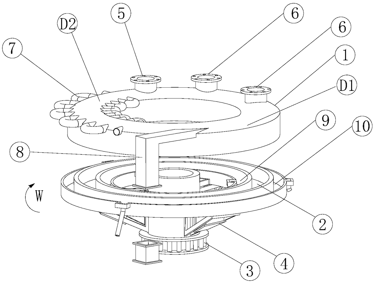
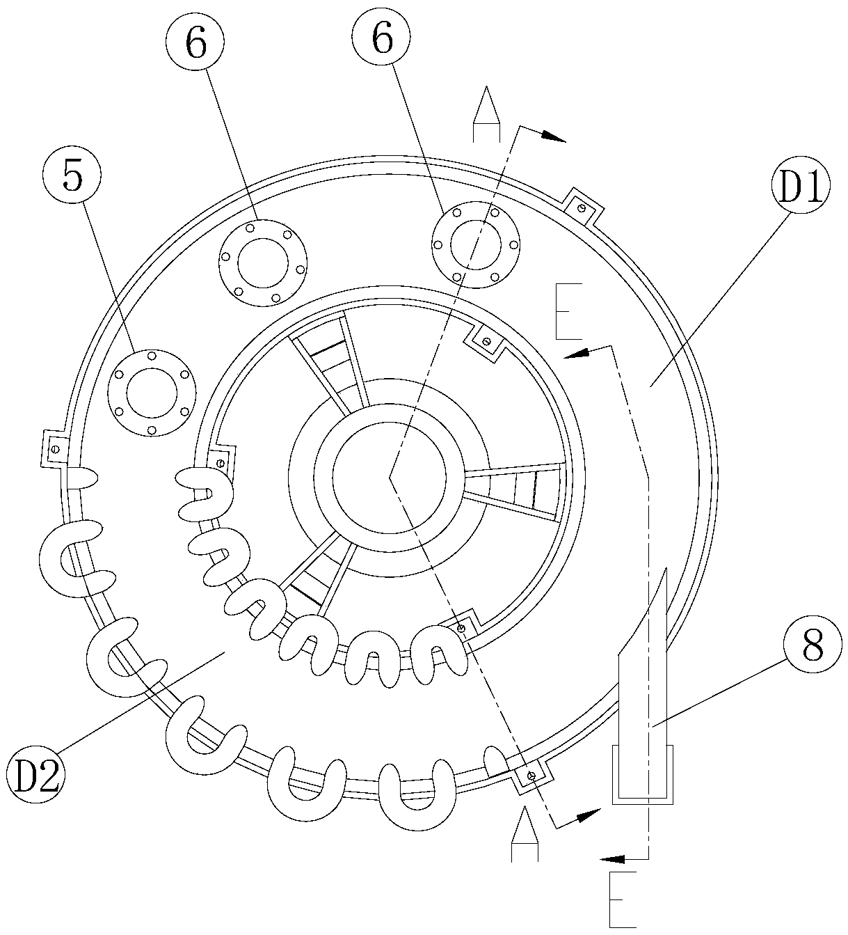
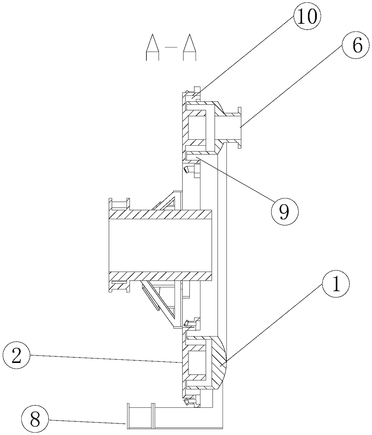
[0065] Specific embodiments of the present invention will be described in detail below in conjunction with the accompanying drawings. It should be understood that the specific embodiments described here are only used to illustrate and explain the present invention, and are not intended to limit the present invention.

[0066] In the present invention, unless stated to the contrary, the used orientation words such as "up, down, top, bottom" generally refer to the directions shown in the drawings or refer to the vertical, perpendicular or gravitational directions The terms used to describe the mutual positional relationship of the various components mentioned above. Orientation words such as "inside, outside" usually refer to the inside and outside of the cavity relative to the center of the cavity. The above orientation words are defined for the convenience of understanding the present invention, and thus do not constitute a limitation to the protection scope of the present in...


PUM


Abstract

The invention discloses a solid heat carrier pyrolyzer. The solid heat carrier pyrolyzer comprises a top cover (1), a bed body (2) and a slewing mechanism, wherein a ring-shaped pyrolyzing tank is formed in the top surface of the bed body; the top cover seals and covers the pyrolyzing tank from the top; a feed opening (5), pyrolyzing gas outlets (6) and a discharge point, which communicate with the pyrolyzing tank are sequentially arranged at intervals in the circumferential direction of a capping ring region corresponding to the pyrolyzing tank in the top cover, in the capping ring region, a fan ring region on one side between the discharge point and the feeding opening is a pyrolyzing region (D1), and a fan ring region on the other side is a reheating region (D2) connected to a heating device; and along with the rotation of the bed body, solid heat carriers in the pyrolyzing tank are reheated through the heating device, the heated solid heat carriers enter the pyrolyzing region to be mixed with pyrolyzing raw materials, then mixed materials are pyrolyzed, one part of pyrolyzed products as pyrolyzed finished products are discharged through the discharge point, and the other part of the pyrolyzed products are circulated to return the reheating region. The pyrolyzer is novel and compact in structure and small in land occupation space, and integrates the functions of pyrolyzing, discharging, heating of solid heat carriers, circulating and the like.

Description

technical field [0001] The invention belongs to the field of coal chemical industry, and in particular relates to a pyrolyzer. Background technique [0002] In the current low-rank coal pyrolysis process, gas heat carrier or solid heat carrier is usually used as the heating heat source. However, there will be a series of technical problems in the project, such as the large diameter of the pipeline caused by the large amount of heat source gas in the gas heat carrier process, engineering problems such as pipeline preparation, valve selection, and high-temperature equipment selection. The selection of high-temperature explosion-proof equipment in the process of screening of medium-high temperature solid heat carrier, horizontal and vertical transportation of heat carrier, reheating of heat carrier, mixing of heat carrier and coal, etc., system safety and air tightness problems in the whole process , as well as problems such as high failure rate and high energy loss in the who...

Claims


Application Information

Patent Timeline
Patent Type & Authority Patents(China)
IPC IPC(8): C10B53/04C10B49/18
CPCC10B49/18C10B53/04
Inventor 麻林孙永伟文成玉赵俊鹏岳媛陈微苌亮郭治郭屹杜万斗秦强
Owner CHNA ENERGY INVESTMENT CORP LTD
Why Eureka
Try Eureka