Electric vehicle for reducing lift force and resistance and increasing mileage

An electric vehicle and lift technology, applied in the direction of the body, body stability, vehicle components, etc., can solve the problems of ignorance of essential characteristics, energy consumption, and poor driving stability of the car, so as to reduce the wake area behind the car, The effect of increasing air velocity and increasing mileage

Active Publication Date: 2017-02-08
徐丹
View PDF6 Cites 3 Cited by
  • Summary
  • Abstract
  • Description
  • Claims
  • Application Information

AI Technical Summary

Problems solved by technology

[0003] The separation of the gas boundary layer on the roof and rear of the electric vehicle will form a low-pressure wake area, which will cause shape resistance and consume a lot of energy when driving. The air under the electric vehicle will cause lift, and the lift will cause the car to poor driving stability
[0004] In order to suppress the gas boundary layer separation and lift problems, electric vehicles at home and abroad have adopted streamlined technology for the appearance of electric vehicles, and adopted measures to speed up the air flow at the bottom of electric vehicles. This aerodynamic structure design does not recognize the aerodynamics of electric vehicles. Due to the essential characteristics of the structure, the effect of suppressing the separation of the gas boundary layer and reducing the lift force is limited, and the range extension and driving stability of electric vehicles are not greatly improved.

Method used


Image

  • Electric vehicle for reducing lift force and resistance and increasing mileage

Examples


Embodiment 1

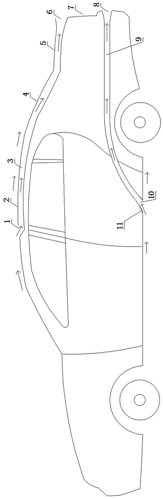
[0038] see figure 1 , in the figure (the direction of the arrow indicates the flow direction of the gas) the air inlet 1 provided on the roof cover, the roof cover flow channel provided with the flow channel, the rear windshield flow channel provided with the flow channel, and the rear luggage provided with the flow channel The flow passages of the box cover are connected in sequence. The air flows to the gas discharge hole II6 through the above-mentioned connected flow channel, and the gas supplements the wake area 7 at the rear of the vehicle.

[0039] The direction of the arrow indicates the flow direction of the gas, and the aerodynamic route is as follows:

[0040] Air→roof air intake 1→roof runner→rear windshield runner→rear trunk lid runner.

[0041] The air flows to the gas discharge hole II6 through the above connected flow channel, and the gas supplements the wake area of ​​the rear of the vehicle.

Embodiment 2

[0043] Present embodiment figure is not drawn. This embodiment is similar in structure to Embodiment 1, and the same parts of the structure will not be repeated here. The air entering the air inlet of the glass runner flows to the runner of the rear trunk lid and / or the runner of the rear bumper together, and the air flows to the gas discharge hole Ⅱ6 and / or gas discharge hole Ⅲ8 through the above connected flow passage, and the gas replenishment vehicle Wake zone 7.

[0044] The direction of the arrow indicates the flow direction of the gas, and the aerodynamic route is as follows:

[0045] Air → Roof Inlet 1 → Roof Runner → Air → Rear Windshield Runner Inlet → Rear Windshield Runner → Rear Deck Lid Runner → and / or Rear Bumper Flow road.

[0046] The air flows to the gas discharge hole II6 and / or the gas discharge hole III8 through the above connected flow channel, and the gas supplements the tail flow area 7 of the vehicle.

Embodiment 3

[0048] Present embodiment figure is not drawn. This embodiment is similar in structure to Embodiment 1, and the same parts of the structure will not be repeated here. The difference is that the roof cover is opened, and the battery pack radiator and / or air-conditioning radiator is placed on the roof cover to open the hole. The radiator fan is used to inhale air, the radiator and fan are provided with flow channels and the roof cover with flow channels, the rear windshield with flow channels, the tailgate cover flow channels with flow channels and / or the set The runner communicates with the rear bumper runner. The incoming air flows to the gas discharge hole II6 and / or the gas discharge hole III8 through the set flow channel, and the gas supplements the wake area 7 at the rear of the vehicle.

[0049] The direction of the arrow indicates the flow direction of the gas, and the aerodynamic route is as follows:

[0050] Air → Roof Air Intake → Roof Lid Battery Pack Radiator and / ...


PUM


Abstract

The invention discloses an electric vehicle for reducing lift force and resistance and increasing mileage. The electric vehicle comprises air power structures arranged at the top tail and bottom of the electric vehicle. An air passage at the top tail of the vehicle weakens the separation of a gas boundary layer, reduces the rear wake area and finally leads the gas into the rear wake area, thus the shape resistance is reduced, and an effect of the electric vehicle of inhibiting gas separation through the air passage to increase the mileage is realized; since the air passage is arranged at the bottom of the electric vehicle, the air density at the vehicle bottom is reduced; the passage leads to left and right rear fenders, a rear bumper and a trunk cover, the air flow path is prolonged, the air speed is increased, and the vehicle lift force is reduced; the air is finally guided to the rear wake area, the wake area is downsized, the shape resistance is reduced, and the effects of the electric vehicle of reducing the vehicle lift force and increasing the mileage through the air passage are realized.

Description

technical field [0001] The invention relates to the technical field of electric vehicles, in particular to an electric vehicle with increased mileage that suppresses gas separation and reduces lift through an air channel. Background technique [0002] With the continuous development of society, electric vehicles have become an important direction for the development of transportation tools. [0003] The separation of the gas boundary layer on the roof and rear of the electric vehicle will form a low-pressure wake area, which will cause shape resistance and consume a lot of energy when driving. The air under the electric vehicle will cause lift, and the lift will cause the car to driving stability deteriorates. [0004] In order to suppress the gas boundary layer separation and lift problems, electric vehicles at home and abroad have adopted streamlined technology for the appearance of electric vehicles, and adopted measures to speed up the air flow at the bottom of electric...

Claims


Application Information

Patent Timeline
Patent Type & Authority Applications(China)
IPC IPC(8): B62D37/02
CPCB62D37/02
Inventor 徐丹
Owner 徐丹
Why Eureka
Try Eureka