Display panel and display device

A display panel and display device technology, which is applied to static indicators, instruments, nonlinear optics, etc., can solve the problems of poor display effects of display panels and display devices, achieve poor display effects, improve display effects, and avoid dark lines The effect of the phenomenon

Active Publication Date: 2019-06-25
TCL CHINA STAR OPTOELECTRONICS TECH CO LTD
View PDF4 Cites 0 Cited by
  • Summary
  • Abstract
  • Description
  • Claims
  • Application Information

AI Technical Summary

Problems solved by technology

[0006] The purpose of the present invention is to provide a display panel and a display device that can improve the display effect of the display panel; to solve the technical problem that the display effect of the existing display panels and display devices is relatively poor

Method used


Image

  • Display panel and display device
  • Display panel and display device

Examples


Embodiment Construction

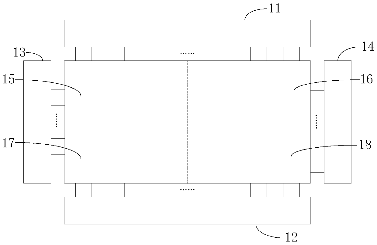
[0037] The following descriptions of the various embodiments refer to the accompanying drawings to illustrate specific embodiments in which the present invention can be practiced. The directional terms mentioned in the present invention, such as "up", "down", "front", "back", "left", "right", "inside", "outside", "side", etc., are for reference only The orientation of the attached schema. Therefore, the directional terms used are used to illustrate and understand the present invention, but not to limit the present invention.

[0038] In the figures, structurally similar units are denoted by the same reference numerals.

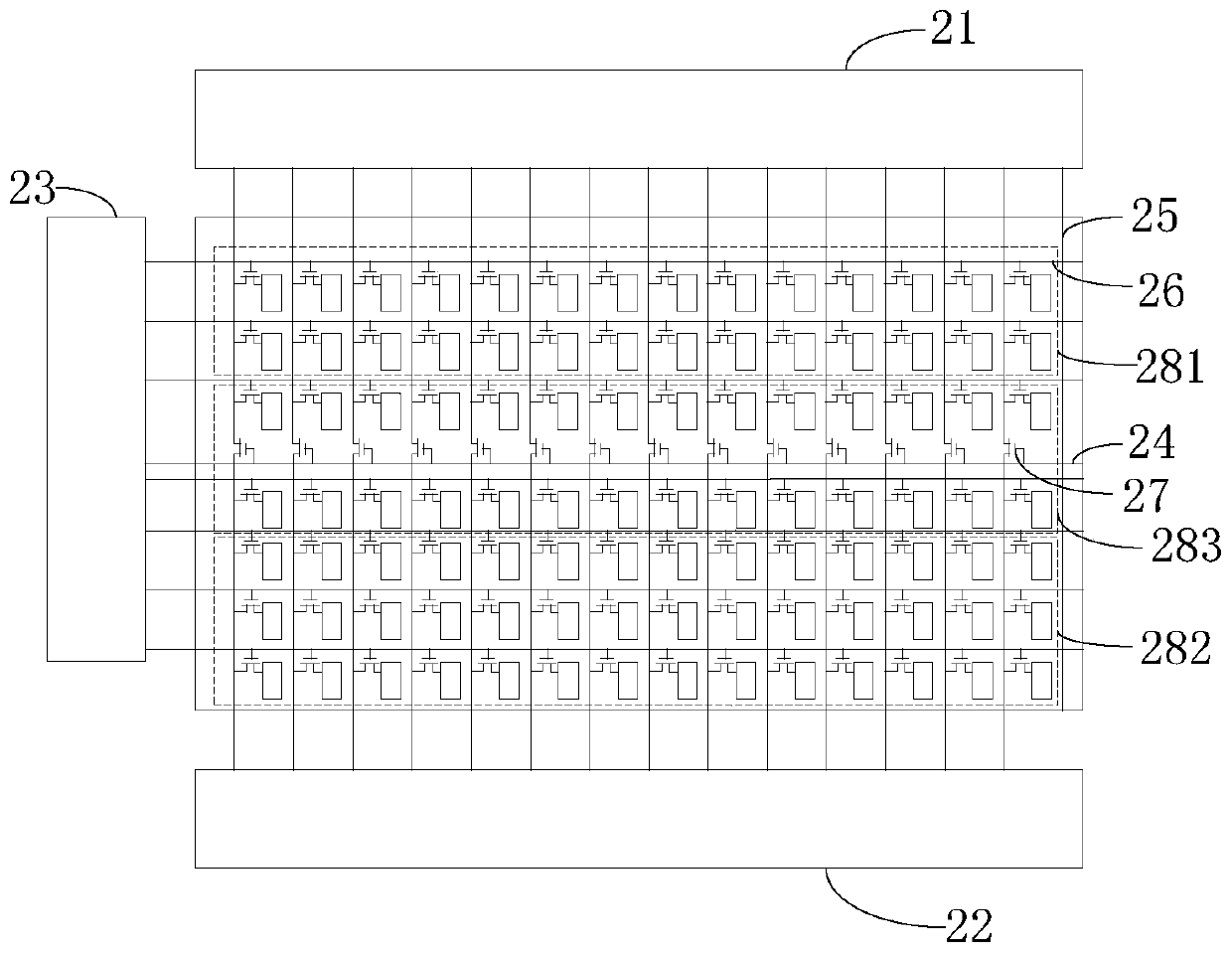
[0039] Please refer to figure 2 , figure 2 It is a schematic diagram of the driving structure of the pixel unit of the preferred embodiment of the display panel of the present invention. The display panel of this preferred embodiment includes a display panel body, a first data line driving circuit 21 , a second data line driving circuit 22 , a scanning l...


PUM


Abstract

The invention provides a display panel. The display panel comprises a display panel body, a first USB cable drive circuit, a second USB cable drive circuit, a scanning cable drive circuit and a switch tube control cable. A pixel unit comprises a first pixel unit driven by a first data signal, a second pixel unit driven by a second data signal and a third pixel unit driven by both the first data signal and the second data signal; the data signal switch tube is arranged in the area of the third pixel unit. The invention further provides a display device. The display panel and the display device achieve the transition display of the third pixel unit placed between the first pixel unit and the second pixel unit by the breakover of the data signal switch tube, avoid the dark-line phenomenon between the first pixel unit and the corresponding second pixel unit, and improve the display effect of the display panel.

Description

technical field [0001] The invention relates to the field of display driving, in particular to a display panel and a display device. Background technique [0002] With the development of TFT technology, the market has higher and higher requirements on the display effect of liquid crystal display panels. High-resolution, large-size products have gradually gained the favor of the market. The resolution ranges from 1920*1080 to 3840*2160 to 8K4K, and it is more likely to develop to 10K in the future. The sizes range from 32 inches, 40 inches, 55 inches to 110 inches and so on. [0003] Due to the large size and high resolution display screen, general use figure 1 The shown structure includes: a first data line driving circuit 11, a second data line driving circuit 12, a first scanning line driving circuit 13, a second scanning line driving circuit 14 and a pixel unit, and the pixel unit is divided into a first area 15, The second area 16, the third area 17 and the fourth ar...

Claims


Application Information

Patent Timeline
Patent Type & Authority Patents(China)
IPC IPC(8): G02F1/1362G09G3/36
CPCG02F1/1362G02F1/136286G09G3/3685G09G2310/0264
Inventor 关晓亮
Owner TCL CHINA STAR OPTOELECTRONICS TECH CO LTD
Why Eureka
Try Eureka