

Double-channel oil feeding type electronic control oil injector with carved grooves
An electronically controlled fuel injection and fuel injector technology, which is applied to machines/engines, fuel injection devices, engine components, etc., can solve the problems of slow response speed of needle valve seating, decreased reliability of fuel injectors, and difficult response characteristics, etc. Achieve the effect of improving control accuracy and flexibility, improving needle valve response characteristics, and reducing abnormal fuel injection conditions
- Summary
- Abstract
- Description
- Claims
- Application Information
AI Technical Summary
Problems solved by technology
Method used
Image

Examples
Embodiment Construction
[0021] The present invention is described in more detail below in conjunction with accompanying drawing example:
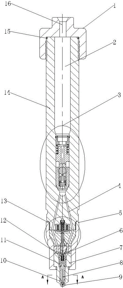
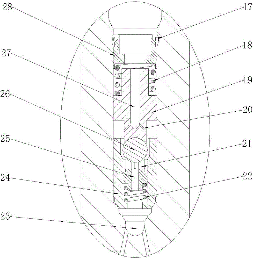
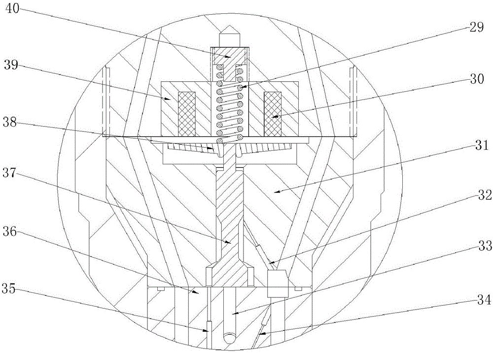
[0022] combine Figure 1-5 , the main structure of the present invention is a two-way oil-feeding electronically controlled fuel injector with grooves, including a fuel injector head 1, a fuel injector body 14, a restrictor valve assembly 3, a solenoid valve assembly 13, a tight cap 5, Needle valve stop sleeve 11, needle valve seat 7, needle valve body 8, nozzle 9. The fuel injector head 1 is connected with the fuel injector body 14 through threads, and is sealed with a sealing ring 15 placed on the fuel injector body 14 . The main oil inlet hole 16 on the injector head 1 communicates with the accumulator chamber 2 in the injector body 14 . Below the injector body 14 is a solenoid valve assembly 13 , a needle valve seat 7 and a needle valve body 8 , which are assembled and connected by a tight cap 5 . The flow limiting valve assembly 3 is placed inside the inje...
PUM
 Abstract
Description
Claims
Application Information