Double-path oil feeding resonance bypass type electrically controlled oil sprayer with engraved groove

An electronically controlled fuel injection and fuel injector technology, which is applied to machines/engines, fuel injection devices, engine components, etc. It can improve the control accuracy and flexibility, reduce the formation of nitrogen oxides, and reduce the fluctuation of fuel pressure.

Pending Publication Date: 2017-04-26
HARBIN ENG UNIV
View PDF8 Cites 0 Cited by
  • Summary
  • Abstract
  • Description
  • Claims
  • Application Information

AI Technical Summary

Problems solved by technology

However, with the gradual increase of the fuel injection pressure in the current fuel injector, the performance of the fuel injector is also tested in various aspects: the fuel injector has static leakage when it is not injecting fuel; the form of two-position two-way valve The dynamic oil return volume is large, which affects the fuel utilization rate; at the beginning of the injection, the fuel injection rate is too high, resulting in an increase in the emission of nitrogen oxides, and after the injection, the control chamber enters the oil in a single way, and the pressure build-up speed is slow, so that the fuel cut-off is not rapid , resulting in the rise of particle emissions; needle valve movement and fuel injection will stimulate water shock pressure waves, resulting in fuel pressure changes in each volume chamber; when a large amount of fuel is injected, the fuel injection process of the fuel injector may affect the fluctuation of the common rail pressure , making the stability and uniformity of the fuel injection process of each cylinder decrease
As the work of the injector increases gradually and the flow rate increases, the degree of cavitation and cavitation in the injector increases significantly, and the reliability of the injector decreases.

Method used


Image

  • Double-path oil feeding resonance bypass type electrically controlled oil sprayer with engraved groove
  • Double-path oil feeding resonance bypass type electrically controlled oil sprayer with engraved groove
  • Double-path oil feeding resonance bypass type electrically controlled oil sprayer with engraved groove

Examples


Embodiment Construction

[0024] The present invention is described in more detail below in conjunction with accompanying drawing example:

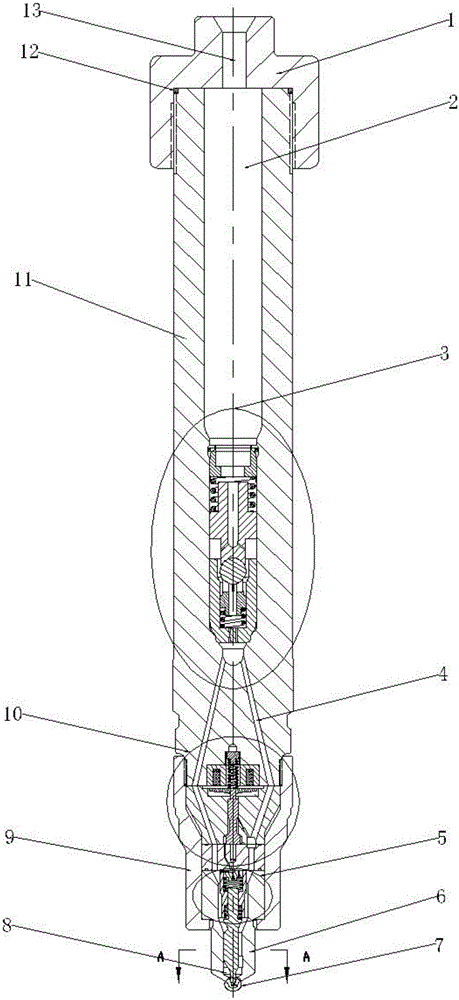
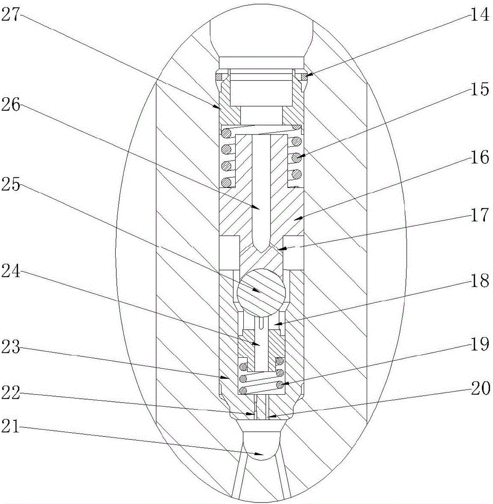
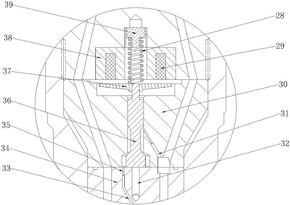
[0025] combine Figure 1-6 , the main structure of the present invention is a two-way oil-inlet resonant bypass type electronically controlled fuel injector with grooves, including a fuel injector head 1, a fuel injector body 11, a restrictor valve assembly 3, a solenoid valve assembly 10, a tight Cap 9, needle valve assembly 5, needle valve seat 6, nozzle 7. The fuel injector head 1 is connected with the fuel injector body 11 through threads, and is sealed with a sealing ring 12 placed on the fuel injector body 11 . The main oil inlet hole 13 on the injector head 1 communicates with the accumulator chamber 2 in the injector body 11 . Below the injector body 11 is a solenoid valve assembly 10 , a needle valve seat 6 and a needle valve assembly 5 , which are assembled and connected by a tight cap 9 . The flow limiting valve assembly 3 is placed inside the inject...


PUM


Abstract

The invention aims to provide a double-path oil feeding resonance bypass type electrically controlled oil sprayer with an engraved groove. The oil sprayer comprises an oil sprayer head, an oil sprayer body, a flow limiting valve assembly, an electromagnetic valve assembly, a needle valve assembly, a nozzle and a needle valve seat, wherein a resonance through hole and a resonance throttling hole are formed in the bottom of the flow limiting valve assembly, so that fluctuation of fuel oil passing through the flow limiting valve assembly is reduced; the electromagnetic valve assembly and the needle valve assembly are arranged below the flow limiting valve assembly; an electromagnetic valve adopts a two-position three-way valve so as to reduce a dynamic oil return volume; a control sliding block is mounted inside a control cavity, and is in contact with a middle block, so that the effects of decreasing the oil spraying rate at the initial stage of spraying and accelerating a seating response of a needle valve; the control cavity adopts a double-path oil feeding mode to further increase the pressure buildup speed and realize the fast response characteristic of the oil sprayer; the engraved groove with a depth in the micron level is formed in the surface of a needle valve body, so that the stability of cavitating flow can be effectively improved, and the cavitation erosion degree of the oil sprayer is reduced; and furthermore, no static pressure difference is generated in the oil sprayer, so that the oil sprayer does not have static leakage.

Description

technical field [0001] The invention relates to an engine fuel injection device. Background technique [0002] The high-speed solenoid valve type fuel injector realizes complex fuel injection rules with the help of the controller, which has the advantages of fast response, high control precision, flexible control strategy and reliable working performance. However, with the gradual increase of the fuel injection pressure in the current fuel injector, the performance of the fuel injector is also tested in various aspects: the fuel injector has static leakage when it is not injecting fuel; the form of two-position two-way valve The dynamic oil return volume is large, which affects the fuel utilization rate; at the beginning of the injection, the fuel injection rate is too high, resulting in an increase in the emission of nitrogen oxides, and after the injection, the control chamber enters the oil in a single way, and the pressure build-up speed is slow, so that the fuel cut-off...

Claims


Application Information

Patent Timeline
Patent Type & Authority Applications(China)
IPC IPC(8): F02M47/02F02M51/06F02M61/10F02M61/18F02M63/00
CPCF02M47/027F02M51/061F02M61/10F02M61/1893F02M63/0017F02M63/0035F02M63/0036F02M63/007
Inventor 范立云刘鹏丁宇宋恩哲
Owner HARBIN ENG UNIV
Why Eureka
Try Eureka