

Double-path oil inlet bypass electric control oil sprayer with carving grooves
An electronically controlled fuel injection and fuel injector technology, which is applied to machines/engines, fuel injection devices, engine components, etc., can solve problems such as affecting the work of fuel injectors, fast starting speed, and easy fluctuations in oil pressure. Improve control accuracy and flexibility, reduce abnormal fuel injection conditions, and reduce the effect of dynamic oil return
- Summary
- Abstract
- Description
- Claims
- Application Information
AI Technical Summary
Problems solved by technology
Method used
Image

Examples
Embodiment Construction
[0023] The present invention is described in more detail below in conjunction with accompanying drawing example:
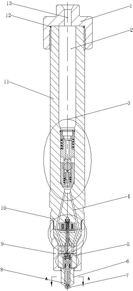
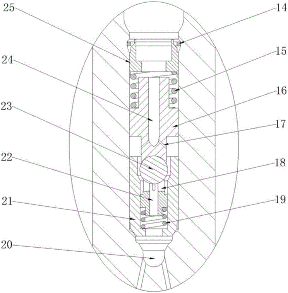
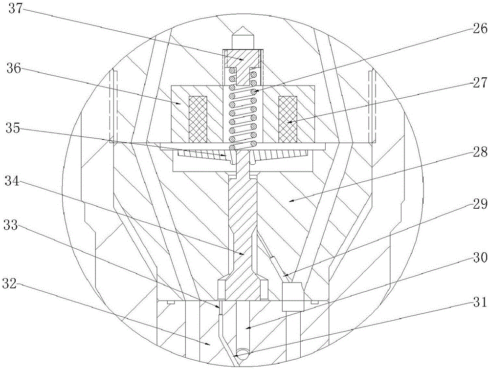
[0024] to combine Figure 1-6 , the main structure of the present invention is a two-way fuel inlet bypass electronically controlled fuel injector with grooves, including a fuel injector head 1, a fuel injector body 11, a restrictor valve assembly 3, a solenoid valve assembly 10, a tight cap 9. Needle valve assembly 5, needle valve seat 6, nozzle 7. The fuel injector head 1 is connected with the fuel injector body 11 through threads, and is sealed with a sealing ring 12 placed on the fuel injector body 11 . The main oil inlet hole 13 on the injector head 1 communicates with the accumulator chamber 2 in the injector body 11 . Below the injector body 11 is a solenoid valve assembly 10 , a needle valve seat 6 and a needle valve assembly 5 , which are assembled and connected by a tight cap 9 . The flow limiting valve assembly 3 is placed inside the fuel injector bo...
PUM
 Abstract
Description
Claims
Application Information