Double-way oil inflow resonance pore plate type electrically-controlled oil injector

An electronically controlled fuel injection and fuel injector technology, which is applied to fuel injection devices, machines/engines, charging systems, etc. Uniformity and other problems, to achieve the effect of reducing abnormal fuel injection conditions, reducing fuel pressure fluctuations, and reducing dynamic fuel return

Pending Publication Date: 2017-05-24
HARBIN ENG UNIV
View PDF8 Cites 0 Cited by
  • Summary
  • Abstract
  • Description
  • Claims
  • Application Information

AI Technical Summary

Problems solved by technology

When a large amount of fuel is injected, the high-pressure common rail oil pressure will fluctuate violently, making the fuel injection process of each cylinder uneven
There is a control plunger in the conventional electronically controlled fuel injector, so that there is a static pressure difference inside the fuel injector, resulting in a large static leakage of the fuel injector

Method used


Image

  • Double-way oil inflow resonance pore plate type electrically-controlled oil injector
  • Double-way oil inflow resonance pore plate type electrically-controlled oil injector
  • Double-way oil inflow resonance pore plate type electrically-controlled oil injector

Examples


Embodiment Construction

[0021] The present invention is described in more detail below in conjunction with accompanying drawing example:

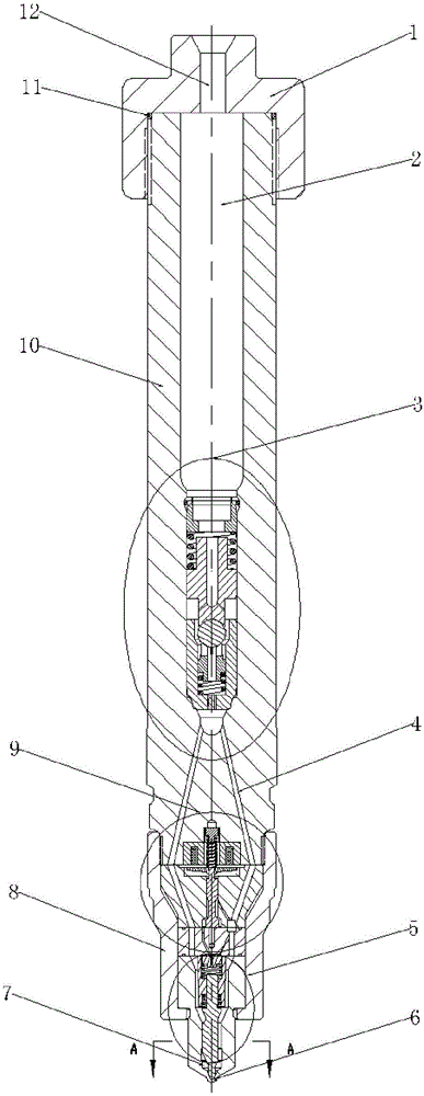
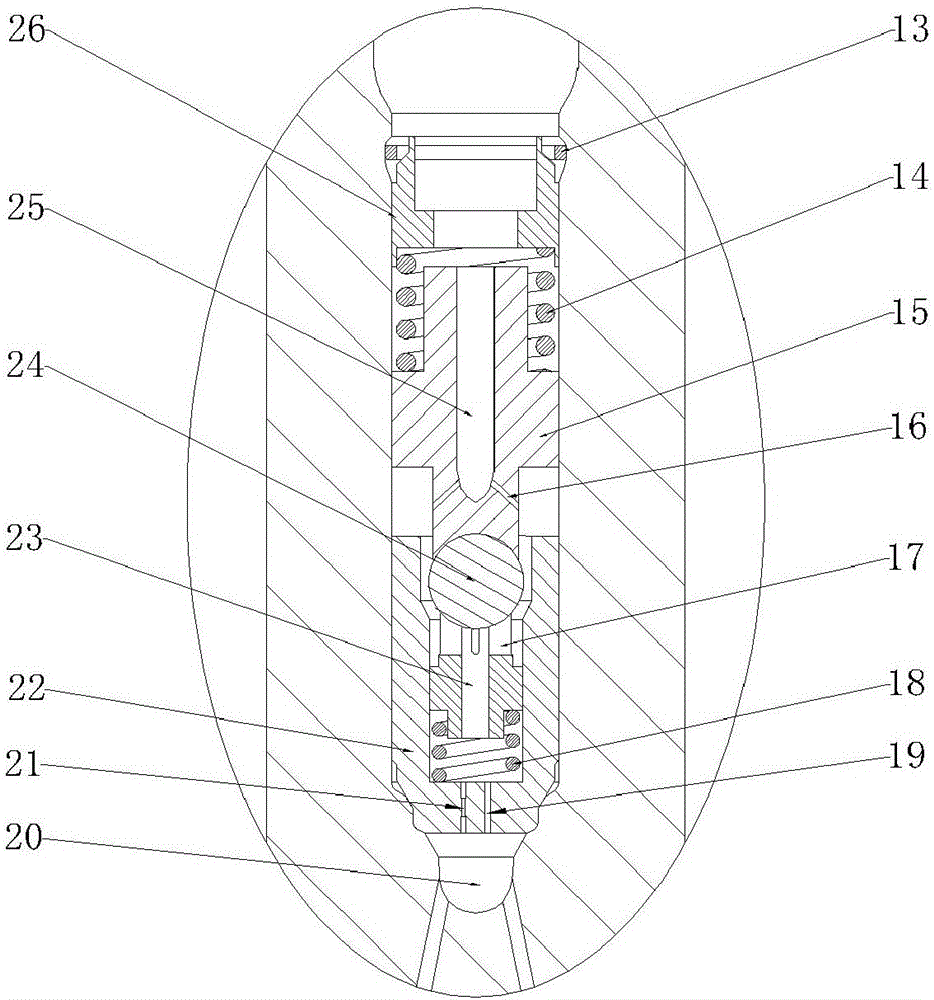
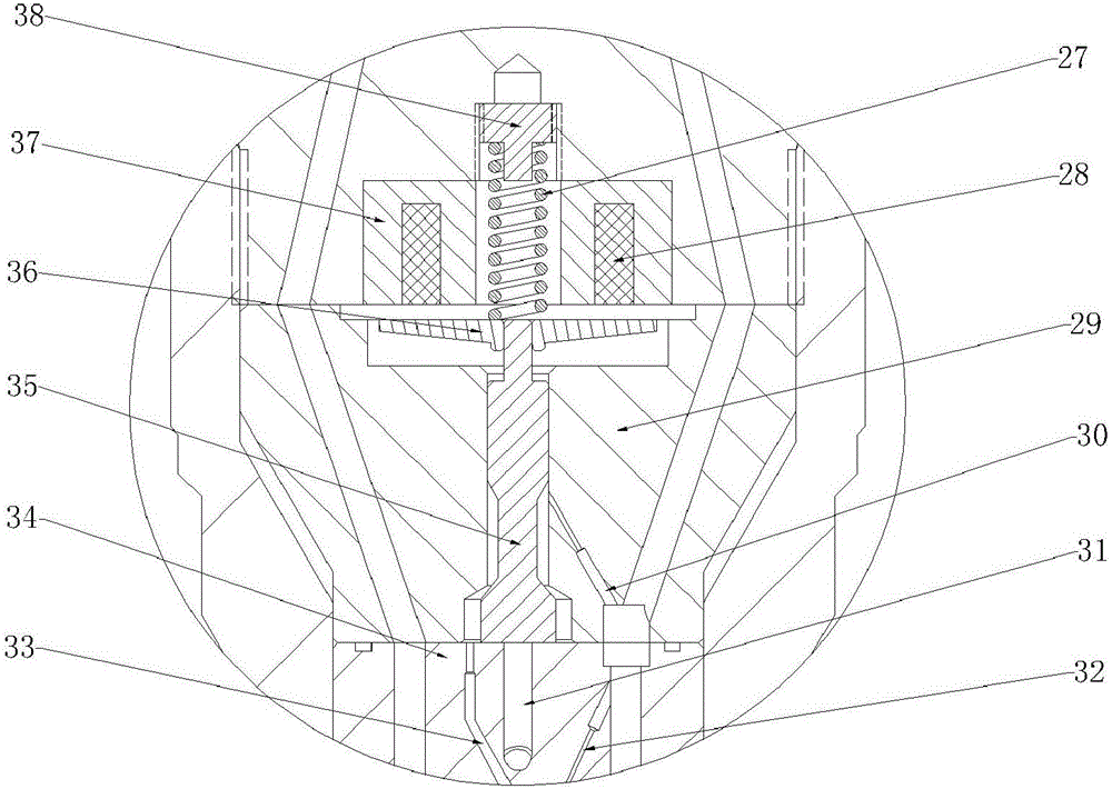
[0022] combine Figure 1-5 , the main structure of the double-inlet resonant orifice electronically controlled fuel injector of the present invention includes a fuel injector head 1, a pressure accumulator chamber 2, a fuel injector body 10, a flow limiting valve assembly 3, a solenoid valve assembly 9, a tight cap 8, Needle valve assembly 5, oil tank 7, spray hole 6. The fuel injector head 1 is connected with the fuel injector body 10 through threads, and is sealed with a sealing ring 11 placed on the fuel injector body 10 . The main oil inlet hole 12 on the injector head 1 communicates with the accumulator chamber 2 in the injector body 10 . Below the injector body 10 is a solenoid valve assembly 9 and a needle valve assembly 5 , which are assembled and connected by a tight cap 8 . The flow limiting valve assembly 3 is placed inside the fuel injector body 10,...


PUM


Abstract

The invention aims to provide a double-way oil inflow resonance pore plate type electrically-controlled oil injector. The oil injector comprises an oil injector head, an oil injector body, a flow limiting valve assembly, an electromagnetic valve assembly and a needle valve assembly. A pressure storage cavity is formed in the oil injector body and communicates with a main oil inlet hole and the flow limiting valve assembly, and the stability of the oil injecting process of each cylinder under the condition of large oil injection quantity is guaranteed. The flow limiting valve assembly is placed below the pressure storage cavity, so that the abnormal oil injection is prevented from being continuously carried out. A resonance structure machined at bottom of flow limiting assembly reduces water hammer pressure waves generated by rapid starting and stopping of the oil injector. Through double-way oil inflow from a balance valve rod of a solenoid valve and the inside of a middle block and double-way oil inflow from a pore plate throttling hole and an annular side surface oil way, the pressure building process of a control cavity is accelerated, and the response speed of needle valve seating is increased. Through a pore plate structure arranged in the control cavity, the dynamic oil return amount in the oil injecting process is greatly reduced, and the characteristic of micro-dynamic oil return is guaranteed.

Description

technical field [0001] The invention relates to an engine fuel injection device. Background technique [0002] Considering the fuel economy and emission indicators of diesel engines, traditional mechanical injectors are gradually being replaced by electronically controlled injectors. Electronically controlled fuel injectors controlled by microcontrollers have the advantages of high control precision and strong information processing capabilities, which are exactly the characteristics that mechanical fuel injectors lack. The current electronically controlled fuel injectors usually use high-speed solenoid valves and are controlled by electrical signals from the electronic control unit. [0003] However, conventional electronically controlled fuel injectors cannot meet the main requirements of modern diesel engines for fuel systems: fuel injectors usually use two-position two-way high-speed solenoid valves, which always have high-pressure fuel flowing through the inlet and out...

Claims


Application Information

Patent Timeline
Patent Type & Authority Applications(China)
IPC IPC(8): F02M47/02F02M61/10F02M61/18F02M63/00
CPCF02M47/027F02M61/10F02M61/1853F02M63/0017F02M63/0035F02M63/0049F02M63/007
Inventor 范立云刘秀琴宋恩哲袁志国
Owner HARBIN ENG UNIV
Why Eureka
Try Eureka