Mechanical vacuum booster with emergency braking function

A vacuum booster and emergency braking technology, applied in the directions of brakes, brake transmissions, transportation and packaging, etc., can solve the problems of large application by the driver and difficult to maintain pedal force, and achieve shortened braking distance and novel structure. , the effect of low cost

Inactive Publication Date: 2013-04-10
WUHU BETHEL AUTOMOTIVE SAFETY SYST
View PDF0 Cites 0 Cited by
  • Summary
  • Abstract
  • Description
  • Claims
  • Application Information

AI Technical Summary

Problems solved by technology

[0004] The invention provides a mechanical vacuum booster with emergency braking function to solve the shortcomings of the conventional vacuum booster that the driver needs to apply a large pedal force and the required pedal force is not easy to maintain when emergency braking is performed, so as to ensure the vacuum The booster has sufficient boosting effect to ensure the braking effect of the whole vehicle

Method used


Image

  • Mechanical vacuum booster with emergency braking function
  • Mechanical vacuum booster with emergency braking function
  • Mechanical vacuum booster with emergency braking function

Examples


Embodiment Construction

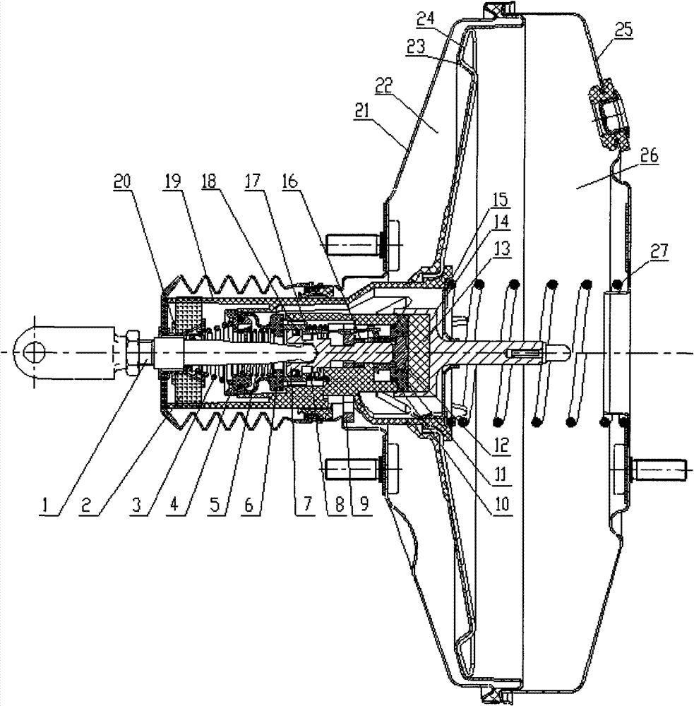
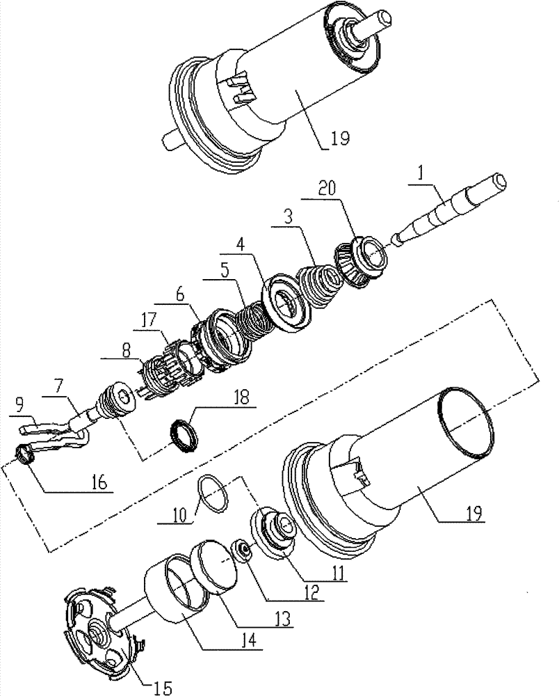
[0030] Explanation of all symbols in the accompanying drawings:

[0031]1-input rod, 1a-step on the input rod, 2-inner filter element, 3-conical spring, 4-spring seat, 5-compression spring, 6-vacuum cup, 6a-end face of vacuum cup bottom, 6b -Inner retaining ring on the vacuum cup, 7-Plunger, 7a-Plunger outer boss, 7b-The first stepped surface of the outer wall of the plunger, 7c-The second stepped surface of the outer wall of the plunger, 7d-Ring groove on the outer wall of the plunger Left end face, 7e-the right end face of the annular groove on the outer wall of the plunger, 7f-the end face of the plunger head, 8-the spring of the trigger mechanism, 9-the locking piece, 9a-the right end face of the middle part of the locking piece, 9b-the end surface of the locking piece, 9c- The left end face of the middle part of the locking piece, 10-rubber sealing ring, 11-valve block, 11a-the step surface on the outer wall of the valve block, 11b-the ring edge on the groove of the outer...


PUM


Abstract

The invention relates to a mechanical vacuum booster with an emergency braking function and belongs to the automobile braking field. A control valve assembly of the mechanical vacuum booster comprises such parts as a valve body, an input link, a filter screen spring seat, a conical spring, a spring seat, a compression spring, a vacuum leather cup, a trigger mechanism, a trigger mechanism spring, a plunger, a locking plate, a locking plate spring, a valve block, a scale plate, a reaction plate, an output link, an elastic collar, as well as a rubber seal ring, a rear shell body, a diaphragm, a diaphragm plate, a front shell body, a large return spring and the like. The mechanical vacuum booster has the advantages of novel structure and low cost; and provided that the vacuum booster meets a certain input power requirement, the vacuum booster can output relatively huge applied force on a main braking cylinder when a driver performs emergency braking, and the vacuum booster maintains output pressure of the main cylinder on the condition of reducing input force, thus shortening the braking distance of the whole automobile and being especially effective for unskilled drivers and drivers who hesitate to brake.

Description

technical field [0001] The present invention relates to a brake vacuum booster, more specifically, to such a brake vacuum booster: the vacuum booster can ensure a certain input power under the condition of emergency braking, and obtain a Increased output force with pressure hold. Background technique [0002] The vacuum booster is a key component in the car braking system. Its function is to use the vacuum generated by the engine intake manifold or the auxiliary vacuum pump to amplify the force of the brake pedal, thereby reducing the force used by the driver for braking. The main principle of the vacuum booster is that the booster has two working chambers, the front and the rear. When the booster is working, the pressure difference between the two working chambers is generated to realize the boosting effect. The two working chambers are separated by the valve body, the diaphragm disc, and the diaphragm. [0003] When the driver applies emergency braking, the conventional v...

Claims


Application Information

Patent Timeline
Patent Type & Authority Patents(China)
IPC IPC(8): B60T13/50B60T13/569
Inventor 刘培郭伟张德志
Owner WUHU BETHEL AUTOMOTIVE SAFETY SYST
Why Eureka
Try Eureka