Utility vehicle having a drive motor and a shifting claw transmission with an electric motor

a technology of electric motor and transmission, which is applied in the direction of toothed gearings, gearing elements, gearings, etc., can solve the problems that the slow-acting electric motor cannot meet the high dynamic requirements, and the electric motor with such large dimensions is very slow to work, so as to achieve the effect of rapid adjustment of the rotational speed of the countershaft and particularly rapid brak

Inactive Publication Date: 2009-04-30
DAIMLER AG
View PDF6 Cites 14 Cited by
  • Summary
  • Abstract
  • Description
  • Claims
  • Application Information

AI Technical Summary

Benefits of technology

[0022]A clutch can be provided between the countershaft and the electric motor. However, omission of such a clutch has certain advantages. For example, given correspondingly small dimensioning of the electric motor, the rotating masses are small compared to the countershaft so that positive and negative accelerations of the countershaft take place very dynamically. Without such a clutch means, no additional actuator elements which could entail disadvantageous dynamic effects are present.
[0023]If the electric motor is energized in a direction opposite to the rotation of the countershaft, the countershaft can be braked particularly quickly.
[0024]By controlling the energization of the electric motor the rotational speed of the countershaft can be rapidly adjusted by means of the electric motor in a simple manner. This provides dynamic advantages, in particular over friction brakes which are not suitable for regulated operation due to their dynamics.

Problems solved by technology

The problems if no blocking synchronization means are used is that in an extreme case the shifting tooth arrangements of the freely rotating wheel of the engaging target gear speed and of the associated shaft could be in tooth-to-tooth positions.
This electric motor does not serve as the sole drive for the utility vehicle, in contrast, for example, to hybrid vehicles, since an electric motor with such large dimensions is very slow-acting.
Such a slow-acting electric motor could not meet the high dynamic requirements which an electric motor has to meet in order to be able to quickly accelerate and / or brake the countershaft for comfortable and rapid gear speed changes.

Method used


Image

  • Utility vehicle having a drive motor and a shifting claw transmission with an electric motor
  • Utility vehicle having a drive motor and a shifting claw transmission with an electric motor

Examples


Embodiment Construction

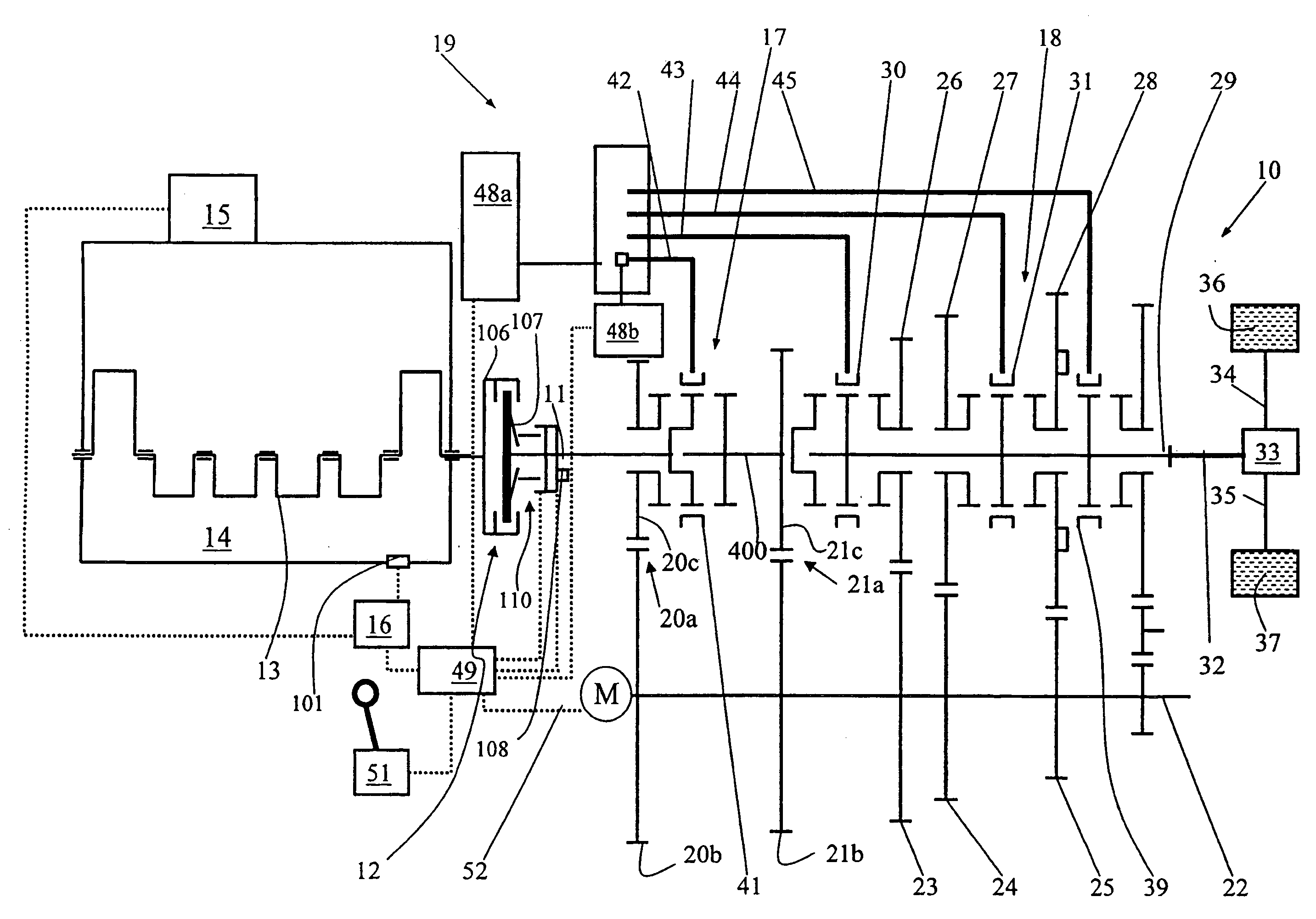
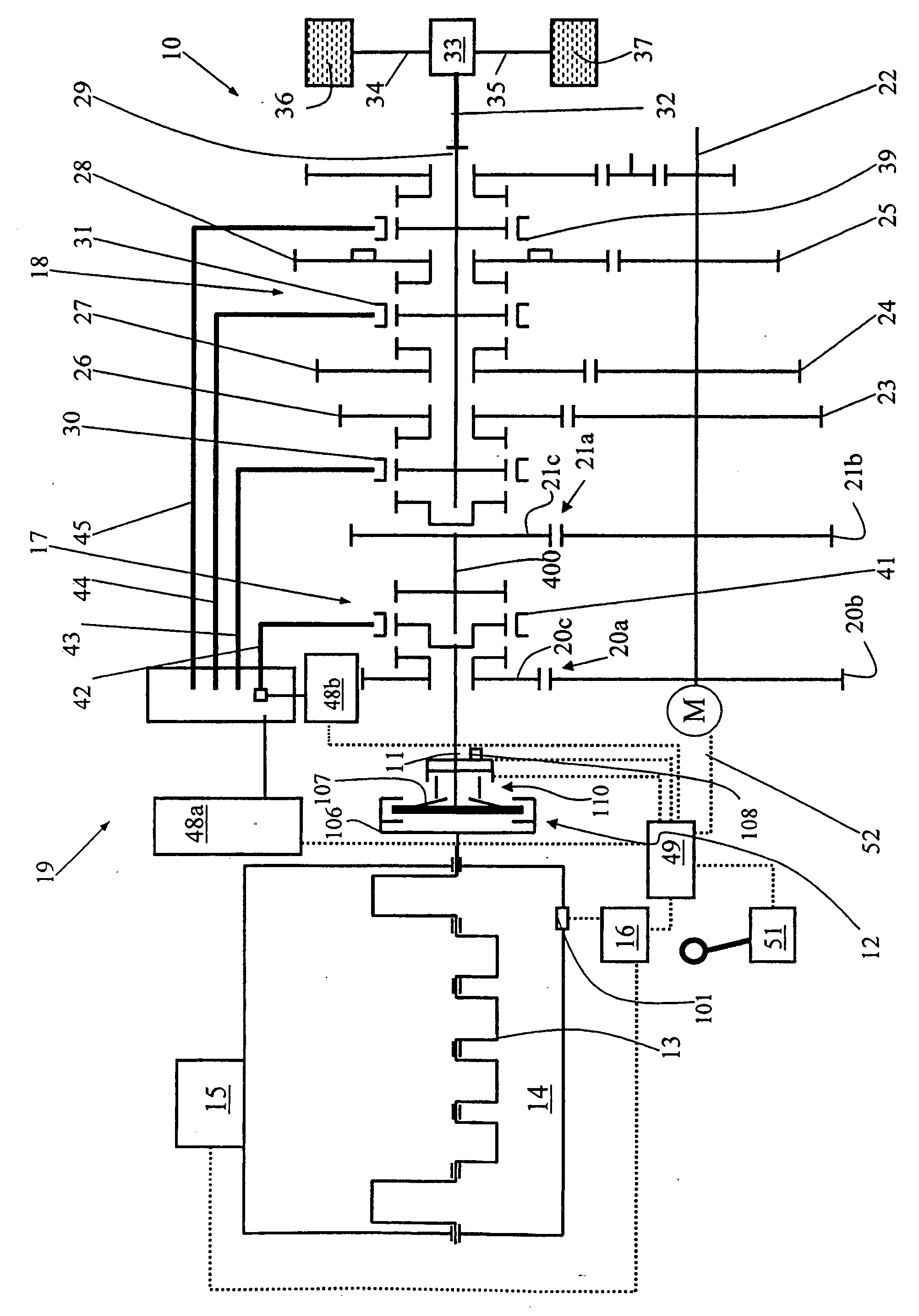
[0027]The drive train 10 comprises a drive motor 14 whose injection system 15 is actuated via a controller device 16. The drive motor 14 is a supercharged diesel engine, as is typical for a utility vehicle. This diesel engine can be, for example, a 6 cylinder or 8 cylinder engine.

[0028]A crank shaft 13 is connected in a rotationally fixed fashion to a primary half 106 of a dry, frictionally locking starter clutch 12 via a crank shaft flange (not illustrated), said starter clutch 12 also forming the flywheel mass of the drive motor 14. This primary half 106 can be coupled in a frictionally locking fashion to a secondary half 107 of the starter clutch 12.

[0029]The starter clutch 12 is arranged axially between the crank shaft 13 and a transmission input shaft 11 of an automated synchronous ring-free shifting claw transmission 19. The starter clutch 12 and the shifting claw transmission 19 are actuated by a transmission controller 49. The transmission controller 49 has a signal-conducti...


PUM


Abstract

In a motor vehicle, in particular a utility vehicle, having a shifting claw transmission and an electric motor connected to a countershaft of the transmission to facilitate central synchronization for gear speed changes, a transmission controller is connected to the electric motor for sensing the electric motor speed and, together therewith the rotational speed of the countershaft based on the induction values present in at the electric motor and sensed by the transmission controller for use in adjusting the energization of the electric motor.

Description

[0001]This is a Continuation-In-Part Application of pending International patent application PCT / EP2006 / 008431 filed Aug. 29, 2006 and claiming the priority of German patent application 10 2005 043 703.6 filed Sep. 14, 2005.BACKGROUND OF THE INVENTION[0002]The present invention relates to a utility vehicle having a drive motor or engine and a shifting claw transmission with an electric motor which can also be operated as a generator.[0003]U.S. Pat. No. 5,560,249 discloses a group transmission with claw clutches in which a power synchronizer which comprises an electric motor is used. The electric motor drives a countershaft via an intermediate gearwheel.[0004]In addition, DE 42 020 83 C2 discloses a different generic type of vehicle transmission with electric drive motor for a hybrid vehicle, a which has a frictionally locking synchronization means and an electric machine. The electric machine can be operatively connected to a countershaft so that the latter can be used as synchroniz...

Claims


Application Information

Patent Timeline
Patent Type & Authority Applications(United States)
IPC IPC(8): F16H3/38
CPCF16H3/126F16H59/38F16H2061/0422Y10T74/1926F16H61/702Y10T74/19284F16H61/0403
Inventor KRIEGER, KARL-LUDWIGSAGER, FRANK
Owner DAIMLER AG
Why Eureka
Try Eureka