
Loom drive mechanism and control system thereof

A technology of transmission mechanism and control system, applied in looms, textiles, textiles and papermaking, etc., can solve the problems of difficulty in meeting, high manufacturing cost, long time, etc., achieve quick start and braking, low manufacturing cost, and ensure consistency Effect

Inactive Publication Date: 2006-07-19
林东
View PDF0 Cites 14 Cited by
  • Summary
  • Abstract
  • Description
  • Claims
  • Application Information

AI Technical Summary

Problems solved by technology

[0003] The main motor of the above-mentioned existing loom is a three-phase asynchronous motor, and its speed cannot be directly adjusted. When the speed needs to be changed to adapt to changes in the process and environment, it needs to be shut down to replace transmission wheels of different sizes, which is troublesome and difficult to meet the speed change requirements. Weaving, variable weft density weaving and other weaving methods with high technical requirements
At the same time, the speed of the main motor will fluctuate with the fluctuation of the voltage. When the voltage is unstable, the fabric will appear uneven density
Moreover, it takes a long time for the main motor to start, accelerate and brake to decelerate. When starting and braking, the weft of the fabric will be uneven, which will affect the quality of the product.
In addition, the weft-seeking operation needs to be realized through an independent auxiliary motor and auxiliary transmission mechanism, which has a complicated structure and high manufacturing cost.

Method used


Image

  • Loom drive mechanism and control system thereof
  • Loom drive mechanism and control system thereof
  • Loom drive mechanism and control system thereof

Examples


Embodiment 1

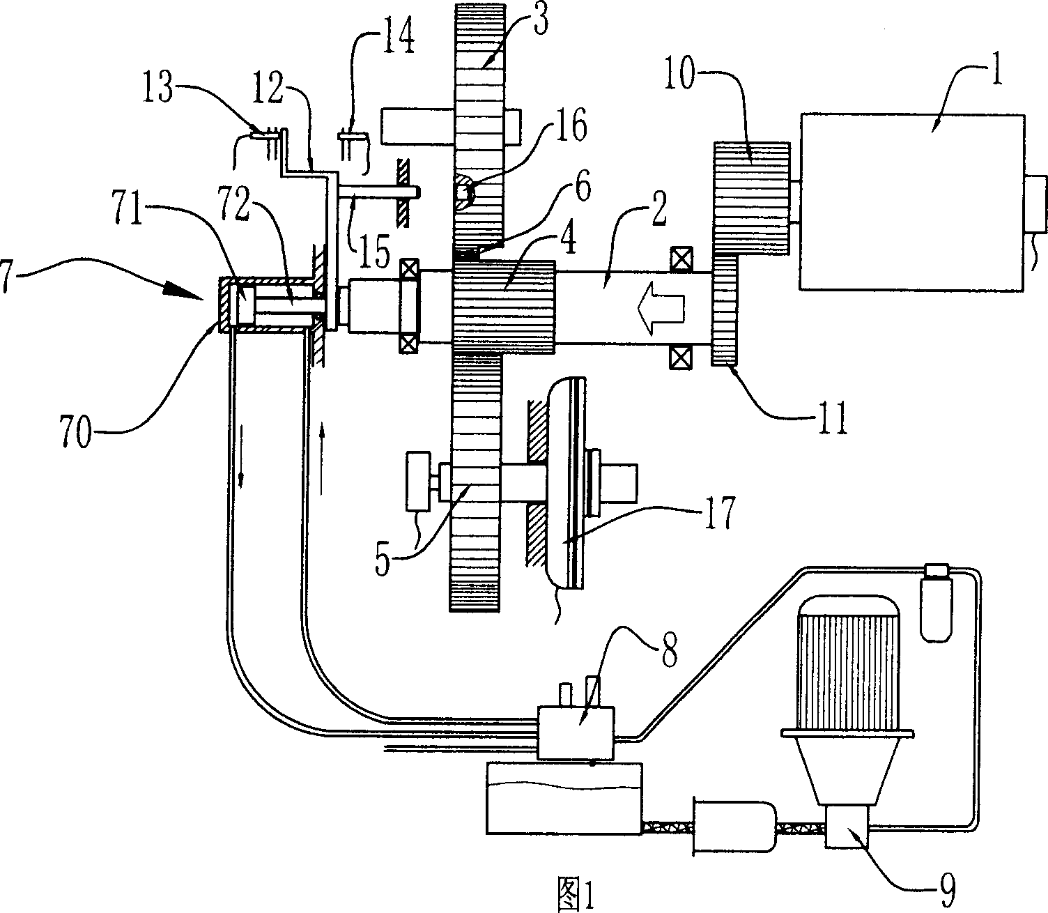
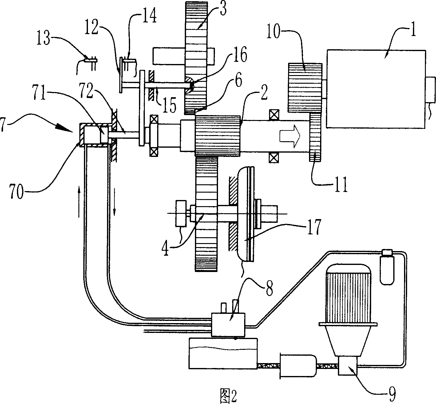
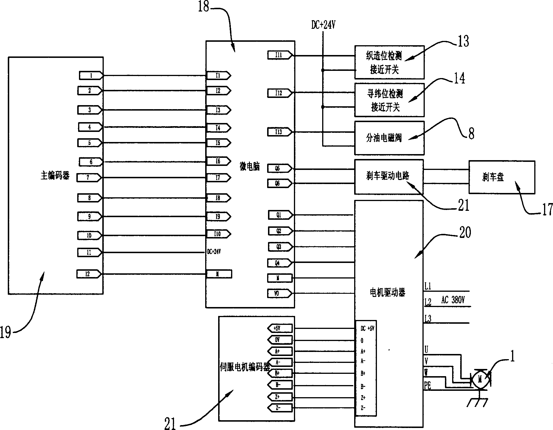
[0020] Embodiment 1, as shown in Figure 1, according to the transmission mechanism of a kind of loom of the present invention, comprise main motor 1 and main shaft 2, main motor 1 and main shaft 2 are meshed by gear, main shaft gear 11 can be relative to main motor gear 10 shafts The main motor 1 is a servo motor, and the main shaft 2 is equipped with a main shaft transmission gear 3. The upper and lower sides of the main shaft transmission gear are respectively meshed with the transmission gear 4 of the weft insertion and beating mechanism and the transmission gear 5 of the shedding mechanism. 4, 5 and the meshing part of the main shaft transmission gear 3 are completely overlapped, a gap 6 is provided on one side of the transmission gear 4 of the weft insertion and beating-up mechanism, and a hydraulic cylinder 7 is provided at one end of the main shaft 2, and the piston 71 is placed in the cylinder body 70 and passed through the rod Part 72 is connected to the main shaft, an...

Embodiment 2

[0032] Embodiment 2, according to the transmission mechanism of another kind of loom of the present invention, it differs from Embodiment 1 in that the meshing parts of weft insertion, beating-up mechanism transmission gear 4 and shedding mechanism transmission gear 5 and main shaft transmission gear 3 are not completely coincident. Figure 5 It is the situation that the meshing parts of the weft insertion and beating-up mechanism transmission gear 4 and the shedding mechanism transmission gear 5 and the main shaft transmission gear 3 are completely staggered. Image 6 It is the situation that the meshing parts of the transmission gear 4 of the weft insertion and beating-up mechanism, the transmission gear 5 of the shedding mechanism and the main shaft transmission gear 3 are partially staggered.


PUM


Abstract

The disclosed loom drive mechanism and its control system comprise a main servo motor to drive a main shaft; wherein, connecting the main shaft to drive mechanism and a transfer gear; engaging the beat-up machine and its transfer gear to the main shaft during some travel and unhitching with the transfer gear during another travel; engaging the opening mechanism transfer gear and the main-shaft transfer gear during whole travel. This invention can drive the opening mechanism directly to find weft without single motor or mechanism and reduce cost, and can realize conveniently a plurality of weaving ways.

Description

technical field [0001] The invention relates to a transmission mechanism of a loom and a control system of the transmission mechanism. technical background [0002] Existing loom, its transmission mechanism has main transmission mechanism and auxiliary transmission mechanism, and its main transmission mechanism is driven by main motor, and auxiliary transmission mechanism is driven by auxiliary motor, and main motor is connected with main transmission shaft by belt transmission. The main motor is a three-phase asynchronous motor, a clutch is installed between the main transmission shaft and the main transmission mechanism, and a clutch is also installed between the auxiliary motor and the auxiliary transmission mechanism. When the loom is weaving, the clutch between the main motor and the main transmission mechanism is combined, and the main motor drives the main transmission mechanism to rotate at high speed, thereby weaving quickly and efficiently. When the weft yarn is b...

Claims


Application Information

Patent Timeline
Patent Type & Authority Applications(China)
IPC IPC(8): D03D51/02
Inventor 林东周天生卢达蒋辉
Owner 林东
Learn More