Drive for a crop picking head

a technology of crop picking head and drive shaft, which is applied in the direction of mowers, agriculture tools and machines, agriculture, etc., can solve the problems of increasing the drive power requirement, increasing the wear rate of the cutting knife and the braking mechanism of the crop picking head, and increasing the rotation speed of the pickup conveyer

Active Publication Date: 2005-12-22
DEERE & CO
View PDF10 Cites 27 Cited by
  • Summary
  • Abstract
  • Description
  • Claims
  • Application Information

AI Technical Summary

Benefits of technology

[0011] The present invention provides a harvesting machine and crop picking head combination that is improved compared to prior-art combinations of this type and that allows an adjustment of the speed of the discharge conveyer relative to the speed of the pickup element of the crop picking head.

Problems solved by technology

The disadvantage of varying the speeds of all driven elements of the crop picking head is that the rotating speeds of the pickup conveyers are increased as well, although such an increase does not improve the harvested crop transport and thus would not actually be necessary.
It increases the drive power requirement, and, for example, in the case of a corn picker head with rotating mowing and feed-in drums, it leads to an increased rate of wear of the cutting knives and braking mechanisms of the crop picking head.
Because of the higher rotating speeds which lead to higher centrifugal forces, corn cobs may be separated from the plants as well and thus be lost to the harvesting process.
This setup ensures that the speed of the discharge conveyer is firmly coupled to the speed of the feed-in conveyer so that at this point transfer problems are no longer to be expected.
However, when the differences between the speeds of the two conveyers are too great, problems may arise during the transfer of the harvested crop from the pickup conveyer to the discharge conveyer.
If, for example, at high forward speeds and long cutting lengths, the pickup conveyer moves considerably faster than the discharge conveyer, jams may occur at the receiving end in the area of the discharge conveyer.
If, at low forward speeds and short cutting lengths, the pickup conveyer moves considerably more slowly than the discharge conveyer, the latter may tear up the harvested crop, which leads to non-uniform cutting lengths.
Another disadvantage of the setup described in WO 02 / 056672 A is that two mechanical drive connections must be disposed between the crop picking head and the harvesting machine.

Method used


Image

  • Drive for a crop picking head
  • Drive for a crop picking head
  • Drive for a crop picking head

Examples


Embodiment Construction

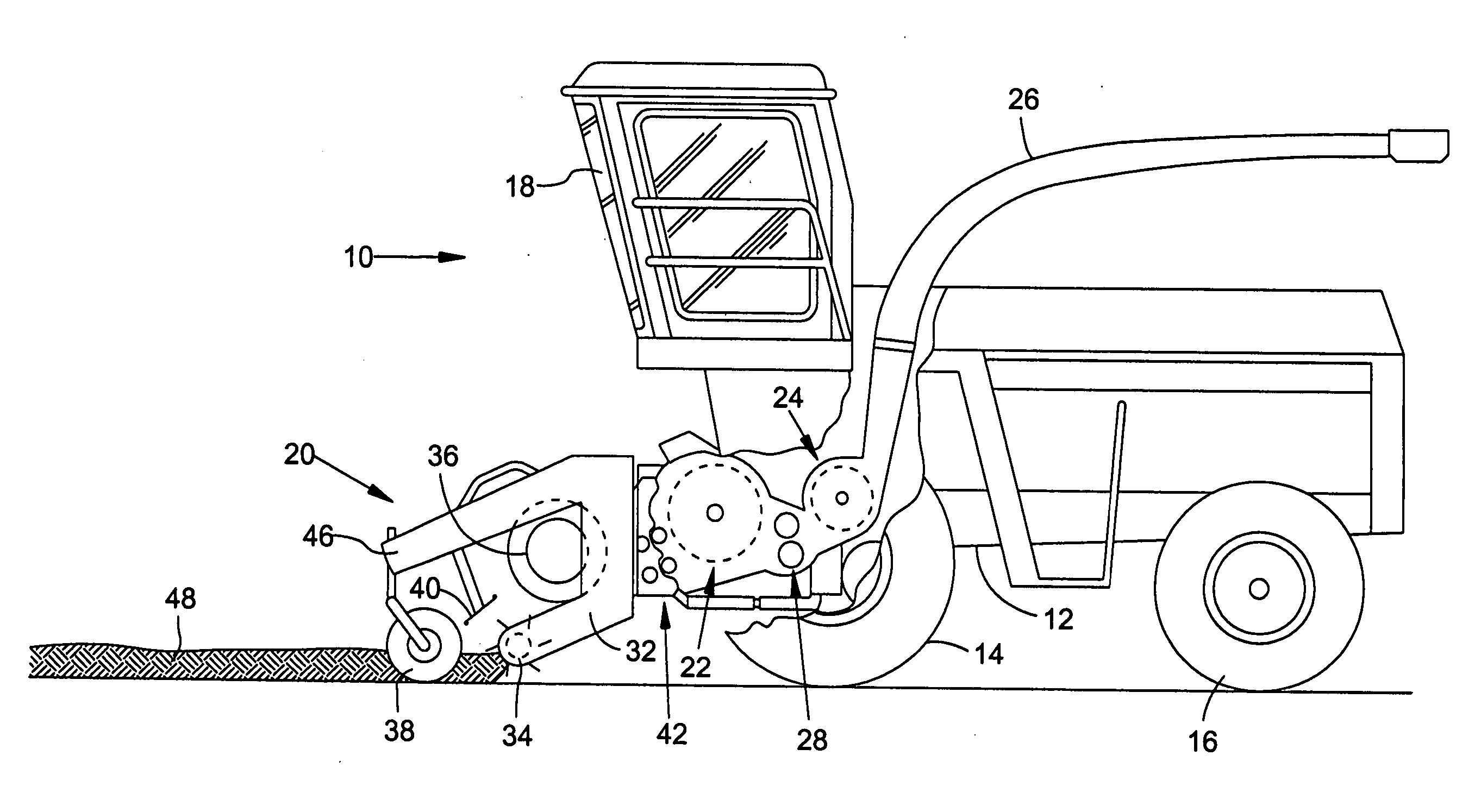
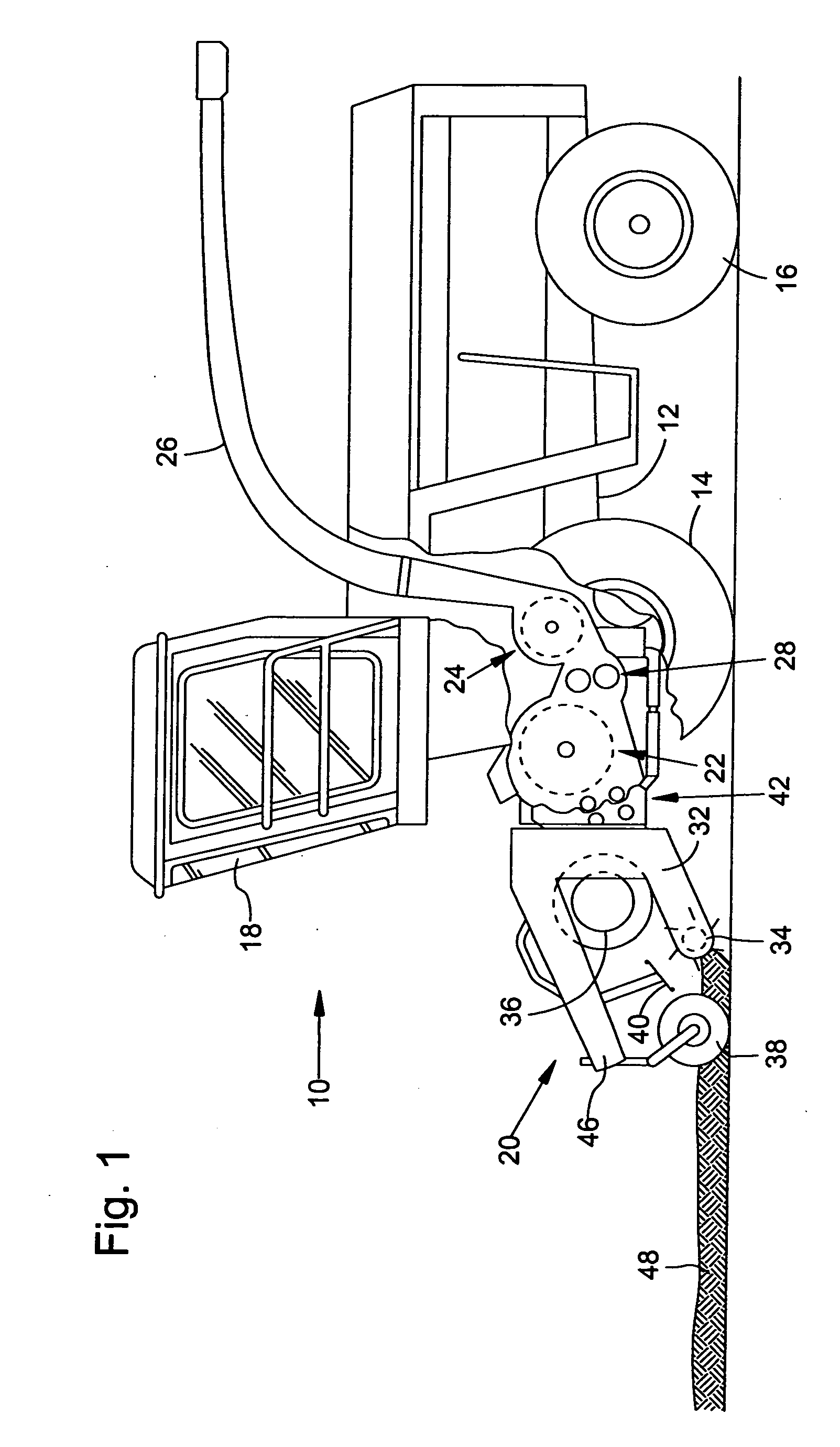
[0029] Referring to the Figures, FIG. 1, shows a harvesting machine 10 in the form of a self-driving field chopper. The harvesting machine 10 comprises a frame 12 which is supported by driven front wheels 14 and steerable rear wheels 16. The harvesting machine 10 is operated from an operator's cabin 18 from which a crop picking head 20 can be seen. The harvested crop, e.g., grass or another crop, that has been picked up off the ground by the crop picking head 20 is fed via a feed-in conveyer 42 with feed rollers that are disposed within a feed-in housing. The feed-in housing is positioned on the front end of the field chopper 10 and feeds the harvested crop to a harvested crop processing unit 22 in the form of a chopper drum which chops the harvested crop into small pieces and transports it to a conveyer 24. The harvested crop leaves the harvesting machine 10 via a tiltable discharge chute 26, which can rotate about an approximately vertical axis, and is discharged into a trailer th...


PUM


Abstract

The agricultural harvesting machine having a crop picking head includes a pickup conveyer which can be driven so as to pick up the harvested crop at a first adjustable speed, a discharge conveyer which can be driven so as to receive the harvested crop picked up by the pickup conveyer, transport the harvested crop, and discharge the harvested crop at a second adjustable speed, and a feed-in conveyer disposed in a feed-in channel of the harvesting machine that can be driven so as to receive the harvested crop from the discharge conveyer, transport the harvested crop, and discharge the harvested crop to a harvested crop processing unit at a third adjustable speed. The third speed and the first speed are independent of one another, and the second speed is defined by the first and third speeds and falls in a range between the first and third speeds.

Description

BACKGROUND [0001] 1. Field of the Invention [0002] The subject matter of the present invention generally relates to an agricultural harvesting machine with a crop picking head. [0003] 2. Related Technology [0004] During harvest operations, agricultural harvesting machines of the present type are moved across a field to pick up or harvest plants by means of a crop picking head, transport them into the harvesting machine where the crop is processed, and finally transfer the processed plants or parts separated therefrom to a transport vehicle. As a rule, the crop picking head generally comprises one or more pickup conveyers which serve to pick up the plants from the soil. For example, prongs of a pickup attachment which pick up hay that has been mown in a previous operation and is ready to be picked up in a swath, or to separate the plants from the roots that remain in the soil and feed them into the crop picking head, such as the mowing and feeding-in drums of a corn picker head. A di...

Claims


Application Information

Patent Timeline
Patent Type & Authority Applications(United States)
IPC IPC(8): A01D43/08
CPCA01D41/142A01D69/06A01D69/005
Inventor CLAUSS, STEFFENBOHRER, STEFANSCHAFER, RAINERHOFER, JURGENPIRRO, PETER
Owner DEERE & CO
Why Eureka
Try Eureka