Method for braking an electric drive motor

a technology of electric drive motor and brake, which is applied in the direction of motor/generator/converter stopper, dynamo-electric converter control, dc motor stopper, etc., can solve the problems of high total weight of work apparatus, inability to replace safety brake devices, and inability to achieve braking times in the process. , to achieve the effect of short braking times and little technical complexity

Active Publication Date: 2015-04-02
ANDREAS STIHL AG & CO KG
View PDF3 Cites 13 Cited by
  • Summary
  • Abstract
  • Description
  • Claims
  • Application Information

AI Technical Summary

Benefits of technology

[0007]It is an object of the invention to provide a method for braking an electronically commutated electric motor, with which very short braking times can be achieved with little technical complexity involved.
[0009]In accordance with the invention, provision is therefore made for the phase connections of the motor phases not to be permanently short-circuited but for a phase short circuit to be connected only via in each case two phase connections for a limited electrical angle of rotation of the rotor, depending on the rotary position of the rotor, which is referred to as controlled short circuit. It has surprisingly been found that, by virtue of this measure of the controlled short circuit, the braking time of a polyphase electric drive motor can be significantly reduced in particular from high rotation speeds. In the case of a three-phase drive motor, braking times which are significantly shorter than in comparison with braking times with a so-called hard short circuit, in which all three phase connections are permanently short-circuited during the entire braking could be achieved from high rotation speeds of approximately 10 000 revolutions per minute. From rotation speeds of 10 000 revolutions per minute, braking times to a standstill of the rotor which are up to 50% lower than in the case of a hard short circuit were measured in the case of a three-phase drive motor.
[0010]Moreover, in the case of the controlled short circuit of a polyphase motor according to the invention, the current loading of the coils and the electronic components is on average lower than in the case of a hard short circuit. The controlled short circuit according to the invention therefore results in significantly shorter braking times with lower current loading of the drive motor and the controlling electronic components.
[0018]By virtue of the braking method according to the invention, quick braking of the rotor to a standstill thereof can be achieved.
[0019]In a simple configuration of the invention, the rotary position of the rotor is established via sensors, expediently via Hall sensors. In a development of the invention, the rotary position of the rotor can also be established without the use of sensors, in particular via the magnitude and / or the profile of the electrical voltage induced in the field coils, however. Alternatively, the rotary position of the rotor can also be determined by evaluation of the induced currents occurring as a result of induction.

Problems solved by technology

The driving electric motor can be braked by short-circuiting its field coils, but the braking times which can be achieved in the process are unsatisfactory and cannot replace a safety brake device.
If handheld, portable work apparatuses are in the form of rechargeable devices the work apparatus has a high total weight owing to the necessary rechargeable battery pack; the additional brake devices required for bringing the tool to a standstill quickly increase this weight further since the safety brake devices are complex in design terms and heavy.

Method used


Image

  • Method for braking an electric drive motor
  • Method for braking an electric drive motor
  • Method for braking an electric drive motor

Examples


Embodiment Construction

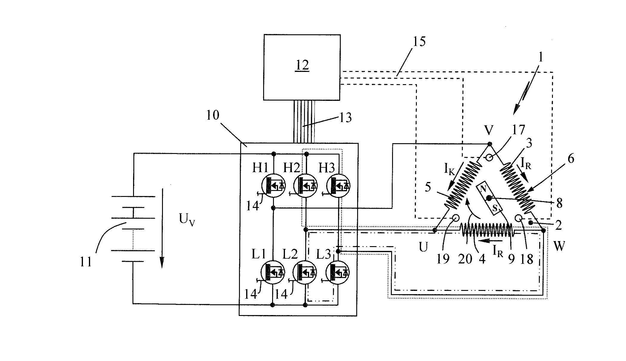
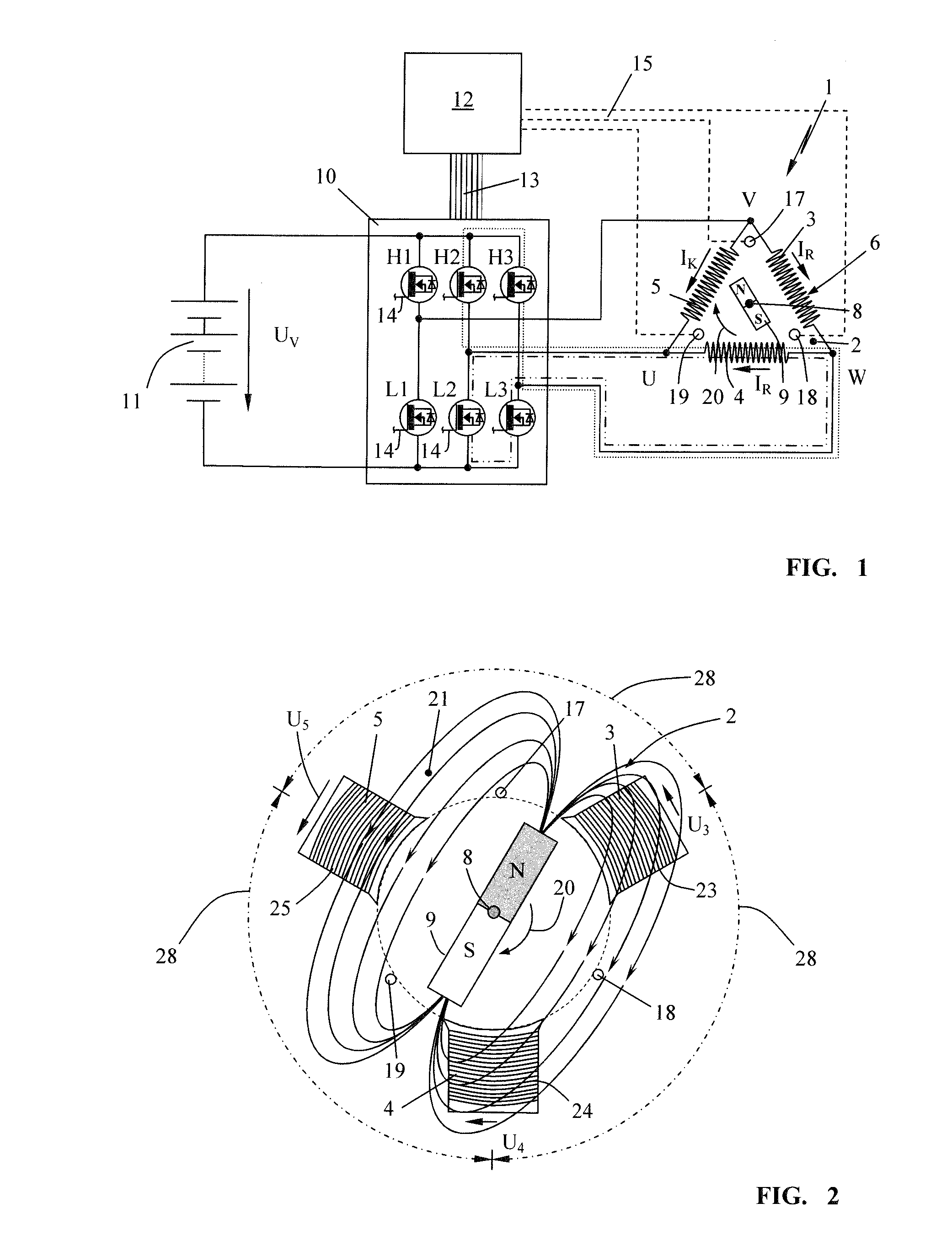
[0037]FIG. 1 shows, schematically, an electronically commutated electric motor 1, which can be in the form of a so-called brushless electronically commutated motor (BEC motor) or electronically commutated motor (EC motor). Such an electronically commutated electric motor 1 comprises a stator 2 comprising field coils (3, 4, 5), which are electrically connected to form a delta circuit 6 in the exemplary embodiment. In this delta circuit 6, the coil ends of adjacent field coils (3, 4, 5) are electrically connected to one another, wherein electrical phase connections U, V and W are formed between in each case two field coils (3, 4, 5) of the coil arrangement. The invention will be explained below with reference to the delta circuit 6; as shown schematically in FIG. 12, the field coils (3, 4, 5) can also be connected to one another in the form of a so-called star circuit 16. In the case of a star circuit, three coil ends are connected to form a common neutral point 7; the remaining coil ...


PUM


Abstract

The invention is directed to a method for braking an electric drive motor having a stator and a rotor. The stator has field coils which have electrical phase connections for three motor phases. To generate an electromagnetic rotating field driving the rotor, the phase connections are connected to a supply voltage via switches actuated by a control unit which closes the switches depending on the rotary position of the rotor. To brake a rotating rotor, a braking current is generated by short-circuiting the phase connections. A phase short circuit is switched in between each two phase connections of the field coils with a preset temporal sequence to brake the rotor. The phase connections short-circuited are each selected corresponding to the rotary position of the rotor so that that field coil is short circuited in which the voltage induced by the magnetic field of the rotating rotor passes through its maximum.

Description

CROSS REFERENCE TO RELATED APPLICATION[0001]This application claims priority of German patent application no. 10 2013 016 216.5, filed Sep. 28, 2013, the entire content of which is incorporated herein by reference.BACKGROUND OF THE INVENTION[0002]Electric drive motors, in particular DC motors or brushless DC motors (EC motors), are known as electric drive for a tool of a handheld work apparatus. Such portable work apparatuses can be drills, rechargeable screwdrivers, motor-operated chainsaws, angle grinders, blowers, brushcutters, hedge trimmers or similar work apparatuses.[0003]In order to operate a brushless electronically commutated three-phase DC motor (BEC motor or merely EC motor), an electronic control unit for an actuation circuit is necessary, by means of which the phase connections of the stator are energized in order to generate a rotating field driving the rotor of the DC motor. Such an actuation circuit is described in U.S. Pat. No. 8,493,011 and preferably comprises el...

Claims


Application Information

Patent Timeline
Patent Type & Authority Applications(United States)
IPC IPC(8): H02P3/22
CPCH02P3/22H02P3/18B27B17/083
Inventor KISCHKA, CLAUDIUSTRINKLE, SIMONNEUBAUER, ANDREASLIEBHARD, GERNOTWICHERT, RENE
Owner ANDREAS STIHL AG & CO KG
Why Eureka
Try Eureka