Starter

A technology for starters and brake pads, which is applied to engine components, engine starting, machines/engines, etc. It can solve the problems that the space cannot be guaranteed, and the helical spline connection cannot be obtained, so as to achieve the effect of high braking performance

Inactive Publication Date: 2005-05-04
SAWAFUJI ELECTRIC COMPANY +1
View PDF1 Cites 14 Cited by
  • Summary
  • Abstract
  • Description
  • Claims
  • Application Information

AI Technical Summary

Problems solved by technology

Therefore, the space for the clutch 163 to rotate in its circumferential direction cannot be secured, and the helical spline connection cannot be obtained by shifting a spline

Method used


Image

  • Starter
  • Starter
  • Starter

Examples


Embodiment Construction

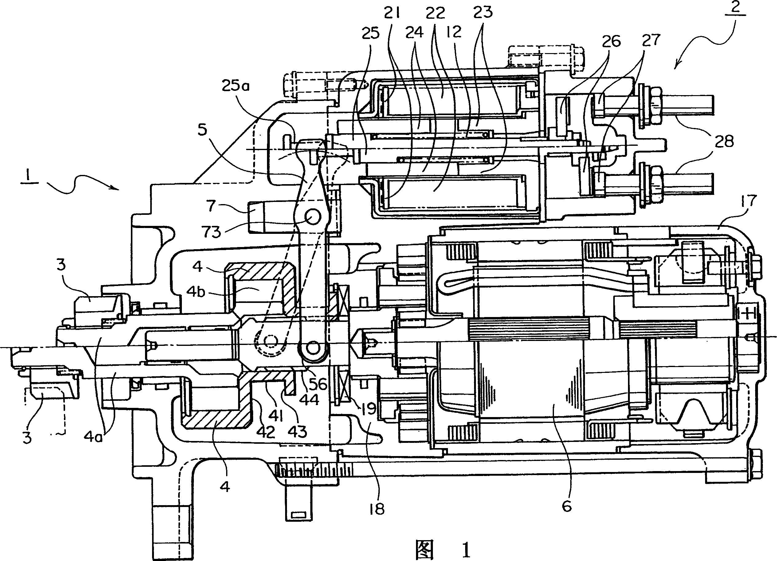
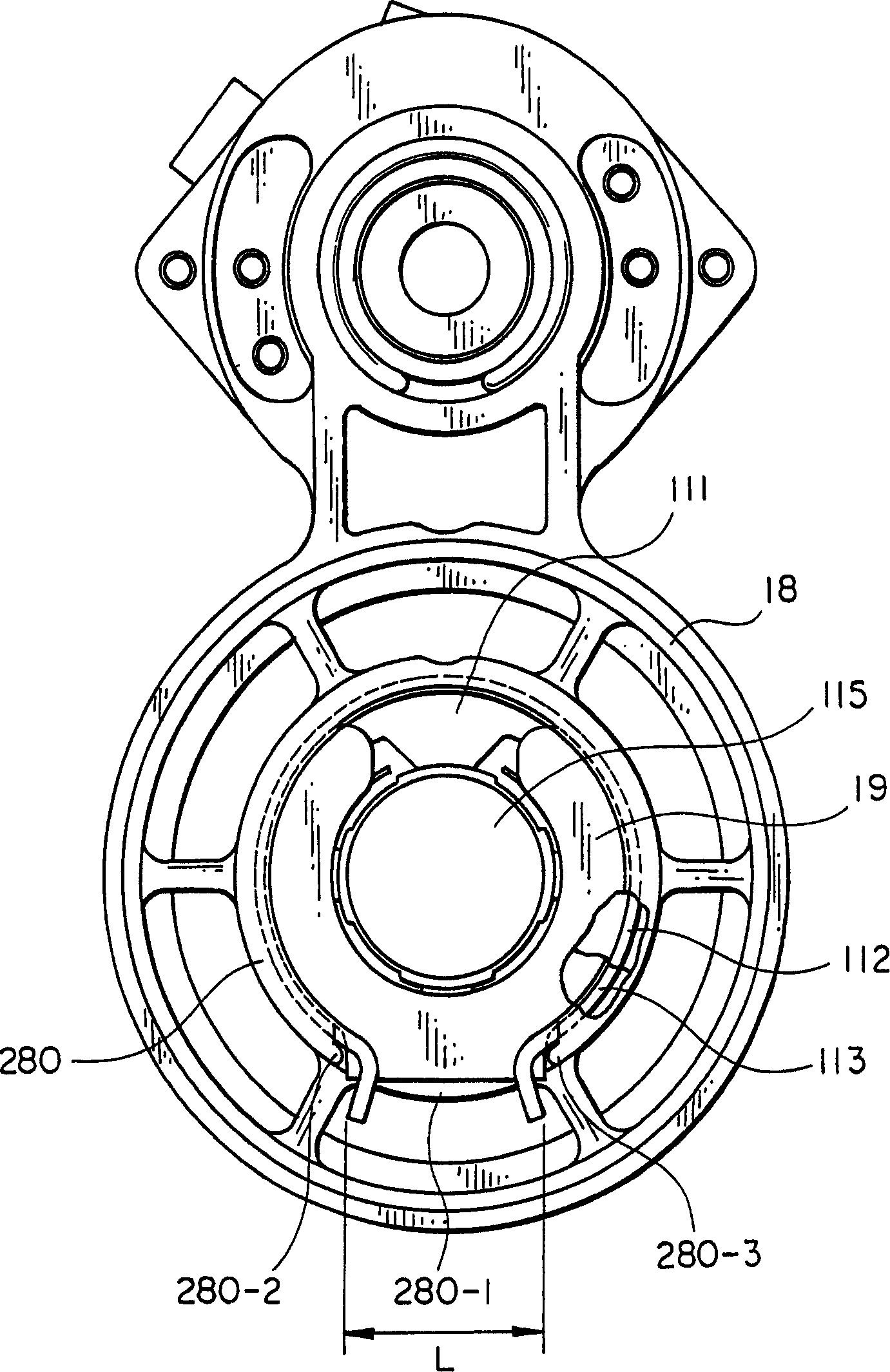
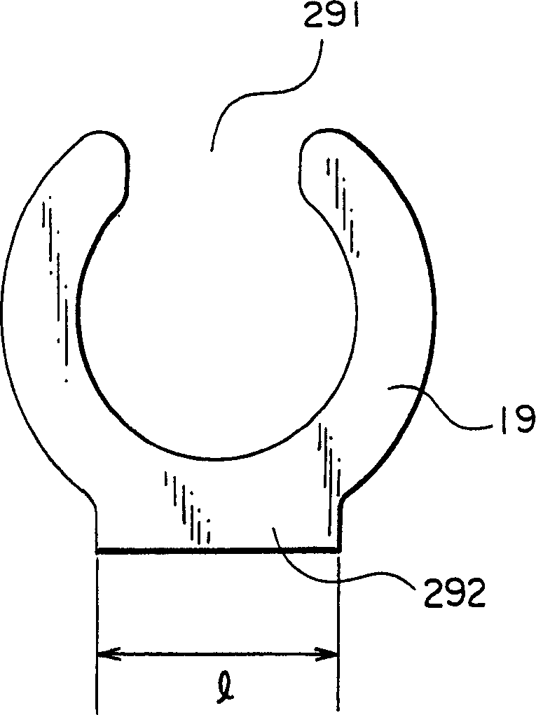
[0043] Fig. 1 is a sectional view of the essential parts of a starter embodiment of the present invention; the parts indicated by reference numerals 1-6 in Fig. 1 are the same as those in a conventional starter, and these parts are the same as those described in the background of the invention above, Their operations have been described in the background invention, so they will not be repeated here. However, by Figure 2-4 Added some more explanations, figure 2 It is the assembly drawing of the center bracket, image 3 is a schematic diagram of the brake pad shape, Figure 4 is a schematic illustration of the ring clamp shape.

[0044] Figure 1 to image 3 , on the wall surface of the gear end of the central support 18 of the motor 6, there is a set for placing such as image 3 An annular concave portion 111 of the annular brake pad 19 is shown, and a ring clamp groove 112 on the inner surface of the concave portion 111 holds the brake pad 19 . This configuration allows...


PUM


Abstract

There is provided a starter in which a brake plate can be assembled or replaced easily. In the starter including a motor which is started by the energization of an armature caused by an ON operation of an electromagnetic switch; a pinion shift lever driven corresponding to the ON operation of the electromagnetic switch; a pinion which is engaged with a ring gear of an engine corresponding to the drive of the pinion shift lever while being rotated corresponding to the start of the motor; and a clutch which is spline connected so that one of the motor output shaft side and the pinion shaft side has splines two times the number of splines of the other and a stopper mechanism utilizing the two-times splines with respect to the axial movement is provided, locking means for detachably fixing a brake plate is provided on a wall surface on the pinion side of a center bracket.

Description

technical field [0001] The invention relates to a starter, which is configured to stop the inertial rotation of the motor quickly when the power supply of the motor is cut off after the engine is started, and also relates to the improvement of the braking mechanism therein. Background technique [0002] Fig. 1 is a sectional view of essential parts of an embodiment of a starter according to the present invention. Through Figure 1, the relationship among the electromagnetic switch, motor, shift fork, gear and clutch in the starter is firstly explained. [0003] Reference numeral 1 among the figure represents a starter, 2 refers to an electromagnetic switch, 3 refers to a gear, 4 refers to a clutch outer ring, 5 represents a shift fork, and 6 represents a motor. [0004] In Fig. 1, the electromagnetic switch 2 includes a driving coil 22 wound on a hollow cylindrical bobbin 21, a fixed iron core 23 fixed on the hollow part of the bobbin 21, and a fixed iron core 23 movably sup...

Claims


Application Information

Patent Timeline
Patent Type & Authority Applications(China)
IPC IPC(8): F02N11/00F02N15/02F02N15/04F02N15/06
CPCF02N15/023F02N15/067Y10T74/134Y10T74/137F02N15/065F02N15/022F02N15/04
Inventor 青木修一梶野定义长谷川洋一
Owner SAWAFUJI ELECTRIC COMPANY
Why Eureka
Try Eureka