An electronic limited slip differential

A technology of limited-slip differentials and differentials, which is applied in the direction of differential transmissions, belts/chains/gears, mechanical equipment, etc., and can solve the problems of vehicles not being able to drive out of slipping areas, locking response time lags, and product reliability No high-level problems, to achieve the effect of short response time of limited slip, small stroke and simple structure

Active Publication Date: 2016-09-14
SPECIAL VEHICLE TECH CENT OF HUBEI AEROSPACE TECH RES INST +1
View PDF6 Cites 0 Cited by
  • Summary
  • Abstract
  • Description
  • Claims
  • Application Information

AI Technical Summary

Problems solved by technology

Likewise, when one axle is on a very slippery surface, such as snow or ice, the wheel on this side spins quickly due to the low friction, and the slipping side axle gear in the differential rotates faster than the non-slip side axle gear. On the slipping side, most of the power is output on the slipping side, the non-slipping side cannot get power, the vehicle loses driving force, and the vehicle cannot drive out of the slipping area
Now there are many forms of differentials that can control vehicle slippage. This kind of differential is called limited-slip differential, but the existing electronic limited-slip differential has a lock-up response time lag, and the limited-slip mechanism is complicated. Disadvantages of low reliability

Method used


Image

  • An electronic limited slip differential
  • An electronic limited slip differential
  • An electronic limited slip differential

Examples


Embodiment Construction

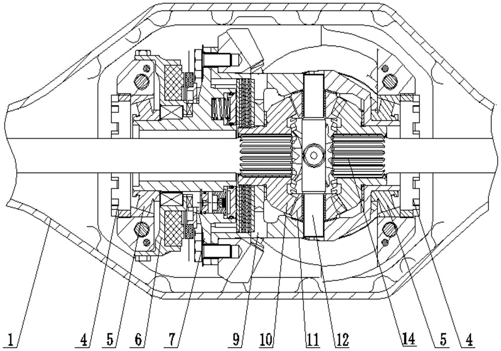
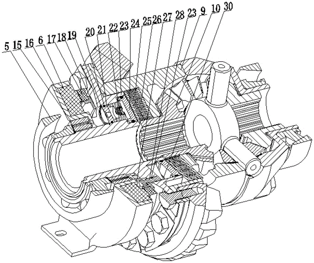
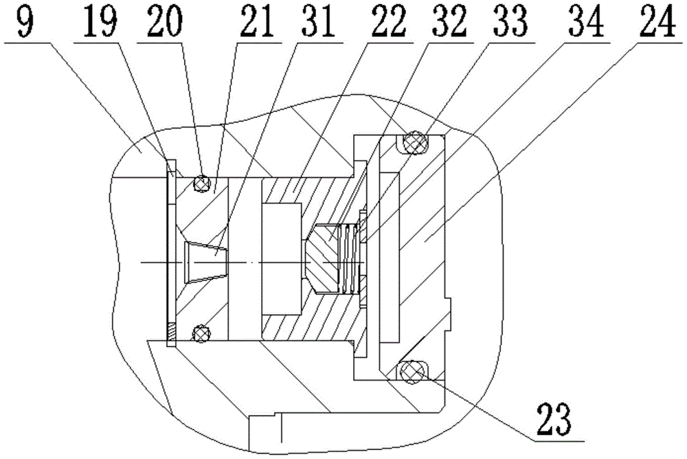
[0017] see Figure 1-Figure 5 The embodiment of the present invention provides an electronic limited-slip differential, including a differential end cover 7, a differential left case 9, a side gear 10, a needle bearing 15, an electromagnetic clutch bracket 16, an electromagnetic clutch 6, Magnet 17, magnet support 18, large piston 24, small piston 28, first sealing ring 23, inner friction plate 25, outer friction plate 26, second spring 30, two exhaust cocks 35 and at least two thrust units (this The inventive embodiment employs three thrust units).

[0018] see figure 1 and figure 2 , the electromagnetic clutch 6 is arranged on the electromagnetic clutch bracket 16, the electromagnetic clutch 6 is supported by the electromagnetic clutch bracket 16, and the electromagnetic clutch 6 is fixed on the differential axle housing 1 by positioning bolts. The electromagnetic clutch support 16 is an annular structure, and the inner side of the electromagnetic clutch support 16 is in...


PUM


Abstract

The invention relates to the technical field of differential mechanisms, particularly to an electronic limited slip differential mechanism. The electronic limited slip differential mechanism comprises a differential mechanism end cover, a needle bearing, an electromagnetic clutch support, an electromagnetic clutch, a magnet, a magnet support, a large piston, a small piston, an internal friction plate, an external friction plate, an air exhaust cock and a thrust unit. The electromagnetic clutch is arranged on the electromagnetic clutch support; the electromagnetic clutch support is mounted on the differential mechanism end cover through the needle bearing; the electromagnetic clutch support is mounted on the differential mechanism end cover through a thrust bearing; the magnet and the electromagnetic clutch are oppositely arranged, and the magnet is connected with the small piston through the magnet support; the large piston is arranged on the right of the small piston; the thrust unit is arranged on the left of the large piston; the right end surface of the large piston abuts against the external friction plate; the external friction plate and the internal friction plate are arranged inside a differential mechanism left casing in a crossed mode; the air exhaust cock is arranged inside the differential mechanism end cover. The electronic limited slip differential mechanism is simple in structure, good in slip limiting effects and short in slip limiting response time.

Description

technical field [0001] The invention relates to the technical field of differentials, in particular to an electronic limited-slip differential. Background technique [0002] In the vehicle transmission system, a differential mechanism is usually used so that the power can be transmitted to the driving wheels on both sides of the same axle of the vehicle or to the two adjacent axles. The former is called the inter-wheel differential, and the latter is called the axle. between differentials. The differential mechanism is generally composed of four planetary gears driven by the casing and two side gears, and the two side gears are respectively connected to the left and right half shafts or the front and rear axles of the vehicle. Normally, the left and right half shafts of the differential rotate with the input gear. But in some special cases, one axis may rotate faster than the other. For example, when the vehicle is cornering, the outside wheels and axle turn faster than t...

Claims


Application Information

Patent Timeline
Patent Type & Authority Patents(China)
IPC IPC(8): F16H48/22F16H48/32
CPCF16H48/22F16H48/32F16H48/34
Inventor 郑建辉袁罕王新郧周谊周跃良陈于阳周祥
Owner SPECIAL VEHICLE TECH CENT OF HUBEI AEROSPACE TECH RES INST
Why Eureka
Try Eureka