
Perforation positioning clamping device

A positioning clamping and positioning pin technology, applied in the mechanical field, can solve the problems of easy loosening of the clamped workpiece and large impact during the clamping process, and achieve the effects of improving service life, reducing impact, and reducing pressing speed

Inactive Publication Date: 2011-10-05
SAIC-GM-WULING AUTOMOBILE CO LTD
View PDF0 Cites 0 Cited by
  • Summary
  • Abstract
  • Description
  • Claims
  • Application Information

AI Technical Summary

Problems solved by technology

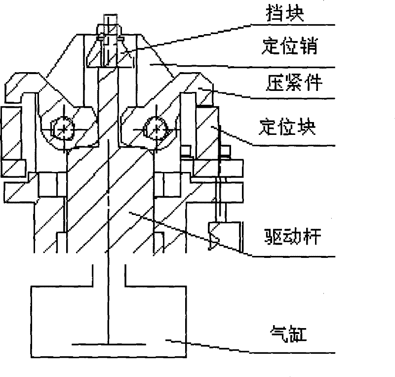
[0005] The clamping principle of this perforated positioning clamping device mechanism is to use levers to transmit force; but due to its own structural reasons, this clamping mechanism causes the driving force of the power device (cylinder) to be transmitted due to space constraints. The force arm is small, so the clamping force of each clamping part at the working position is basically equal to half of the input force or less, and the clamped workpiece is easy to loosen; and the moving speed of the working part of the clamping part is basically greater than or equal to that of the drive rod. Movement speed, large impact during clamping

Method used


Image

  • Perforation positioning clamping device
  • Perforation positioning clamping device
  • Perforation positioning clamping device

Examples


Embodiment Construction

[0018] The following content is a further detailed description of the present invention in conjunction with specific preferred embodiments, and it cannot be assumed that the specific implementation of the present invention is limited to these descriptions. For those of ordinary skill in the technical field of the present invention, without departing from the concept of the present invention, some simple deduction or replacement can be made, which should be regarded as belonging to the protection scope of the present invention.

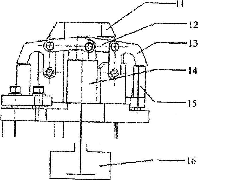
[0019] see image 3 , The present invention provides a positioning and clamping device for perforation, which includes a positioning pin 11 , a connecting rod 12 , a pressing member 13 , a driving rod 14 , a positioning block 15 and a cylinder 16 . Wherein the cylinder 16 is connected with the driving rod 14 and pushes the driving rod 14 , and the connecting rod 12 is connected with the driving rod 14 . The pressing member 13 is connected with the con...


PUM


Abstract

The invention provides a perforation positioning clamping device which comprises a positioning pin, a connecting rod, a compression part, a driving rod, a positioning block and a cylinder. The driving rod and the connecting rod, the compression part and the positioning pin and the compression part and the connecting rod are respectively connected by a hinge to compose a reinforcing hinge structure. The perforation positioning clamping device changes the existing force transmission mode of a lever into a transmission mode of the reinforcing hinge structure. The reinforcing hinge structure is mainly characterized in that the structure has small friction loss and large reinforcing multiple and can obviously reduce the compressing speed of a compression block when the compression block approaches a workpiece, alleviate the impact of compressing force on the workpiece and the compression block and improve the surface quality of the workpiece and the service life of the compression block and the whole mechanism.

Description

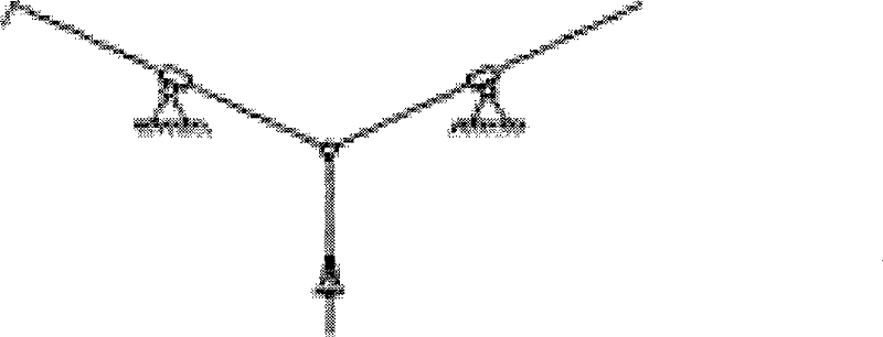
technical field [0001] The invention relates to a mechanical field, in particular to a positioning and clamping device. Background technique [0002] Such as figure 1 as well as figure 2 As shown in the prior art, the perforated positioning and clamping device used for positioning and clamping the front wheel house welded part of the body part includes a stopper, a positioning pin, a pressing piece, a positioning block, a driving rod and a cylinder. [0003] The perforated positioning and clamping device works by using positioning pins and positioning blocks to position the existing holes or designed process holes and positioning surfaces on the workpiece, and at the same time, the two pressing parts swing around their respective rotation centers to achieve positioning of the workpiece. Clamping action on both sides. [0004] The working process of this mechanism: when the cylinder pushes the driving rod forward, one end of the driving rod contacts the bottom end of the ...

Claims


Application Information

Patent Timeline
Patent Type & Authority Patents(China)
IPC IPC(8): B23K37/04B23K37/053
Inventor 孟大庆雷志华郑宏良唐高中
Owner SAIC-GM-WULING AUTOMOBILE CO LTD
Learn More