Eureka AIR delivers breakthrough ideas for toughest innovation challenges, trusted by R&D personnel around the world.

Blast furnace slag bottom filter tank system and blast furnace slag bottom filter method treatment process

A bottom filter, blast furnace slag technology, applied in the direction of filtration treatment, sedimentation treatment, special treatment targets, etc., can solve the problems of reducing the filtration speed and efficiency of the filter layer, reducing the water pressure of the bottom filter tube, and reducing the equipment operation rate, etc. The effect of eliminating backwashing dead zone, simplifying pipe network layout and improving service life

Pending Publication Date: 2022-02-08
MCC CAPITAL ENGINEERING & RESEARCH
View PDF0 Cites 0 Cited by
  • Summary
  • Abstract
  • Description
  • Claims
  • Application Information

AI Technical Summary

Problems solved by technology

In actual use, the main factors affecting the efficiency of slag-water separation are the filtration rate and separation effect of the filter layer: the filter layer is too tight, resulting in slow filtration speed, long time for slag-water separation, and high water content in the slag, which cannot Realize reasonable recycling of water resources, resulting in waste of water resources; the filter layer is too sparse, resulting in fine slag particles that cannot be filtered out, causing fine slag particles and liquid water to enter the water circulation system, causing damage to the pipelines, valves, and pumps of the water circulation system. Cause serious wear and tear, increase equipment maintenance and overhaul costs, reduce equipment operation rate, and affect the normal operation of the water slag system
[0003] The blast furnace slag water contains a certain amount of slag wool. During the separation process of slag and water, the slag wool is easy to block the filter pores in the filter layer, resulting in hardening of the slag layer. The hardened filter layer reduces the filtration speed and efficiency, resulting in slag Water system production cannot proceed smoothly
Production practice shows that the problem of filter layer compaction has become a difficult problem that needs to be solved urgently, especially in northern China, where the water quality of slag flushing is relatively high, which increases the possibility of filter layer compaction. Once the filter material is compacted, replace it. The difficulty increases, which will seriously affect the production rhythm of the blast furnace
In order to avoid or slow down the hardening problem of the filter layer, the filter material is backwashed by using the bottom filter pipe where the slag flushing water enters the bottom of the filter tank. The effect is not ideal
At the same time, most of the existing bottom filter pipes are of long pipe structure. After the water pressure flows out from the flow hole on the bottom filter pipe, the water pressure in the bottom filter pipe will be gradually reduced, so that there is a blind area for backwashing in the bottom filter pipe.
Since the blind area cannot be washed in all directions, the blind area is the main area where the filter material is compacted. If the filter material is not treated in time after the compaction, it will gradually expand or even connect into pieces, which will seriously affect the filtration efficiency of the filter tank.

Method used


Image

  • Blast furnace slag bottom filter tank system and blast furnace slag bottom filter method treatment process
  • Blast furnace slag bottom filter tank system and blast furnace slag bottom filter method treatment process
  • Blast furnace slag bottom filter tank system and blast furnace slag bottom filter method treatment process

Examples


Embodiment Construction

[0093] The details of the present invention can be understood more clearly with reference to the accompanying drawings and the description of specific embodiments of the present invention. However, the specific embodiments of the present invention described here are only for the purpose of explaining the present invention, and should not be construed as limiting the present invention in any way. Under the teaching of the present invention, the skilled person can conceive any possible modification based on the present invention, and these should be regarded as belonging to the scope of the present invention. It should be noted that when an element is referred to as being “disposed on” another element, it may be directly on the other element or there may also be an intervening element. When an element is referred to as being "connected to" another element, it can be directly connected to the other element or intervening elements may also be present. The terms "mounted", "connec...


PUM

PropertyMeasurementUnit
diameteraaaaaaaaaa
particle diameteraaaaaaaaaa

Abstract

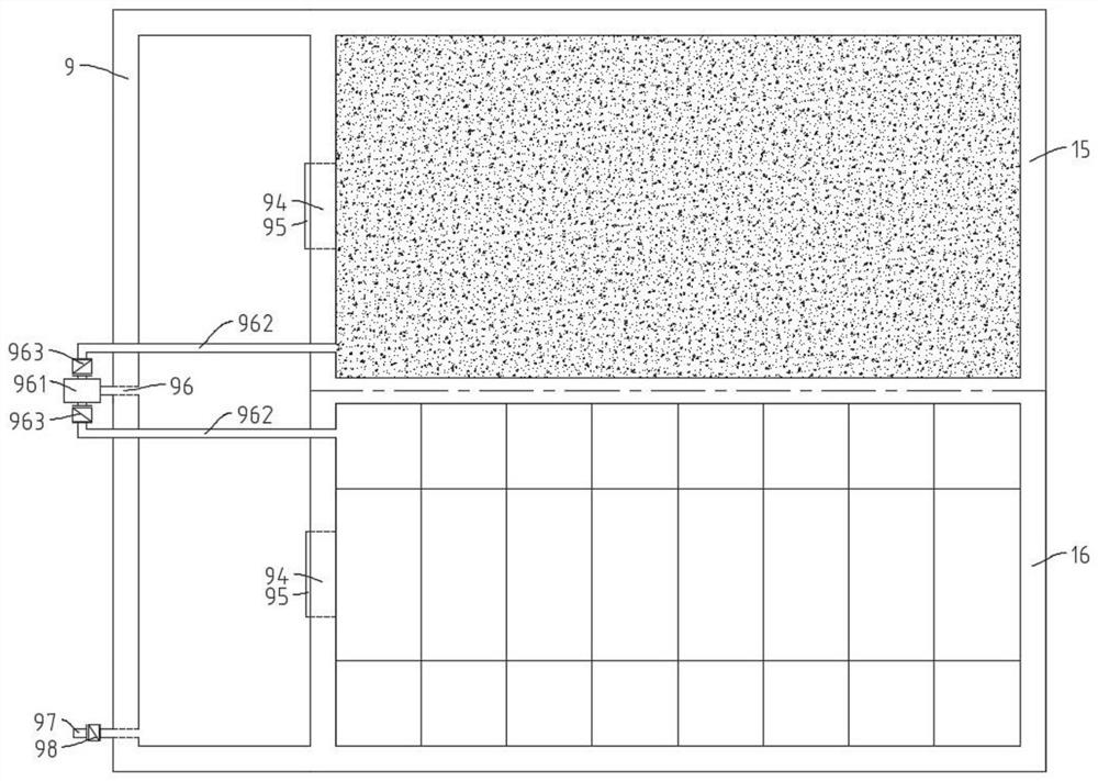
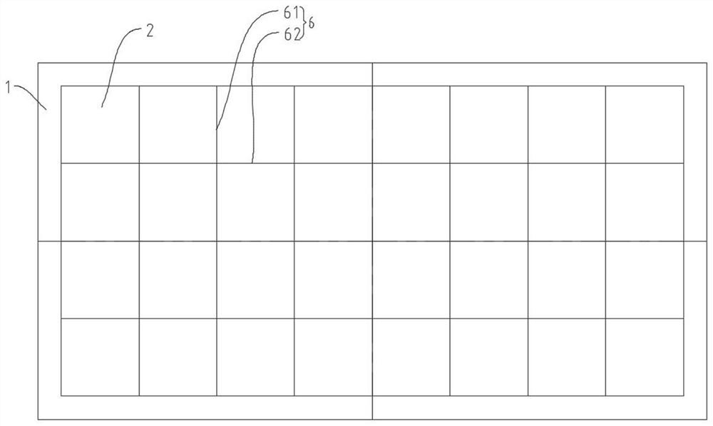
The invention discloses a blast furnace slag bottom filter tank system and a blast furnace slag bottom filter method treatment process, and relates to the field of metal smelting equipment. The blast furnace slag bottom filter tank system comprises a water storage tank and at least one bottom filter tank. A modular filter layer is arranged in the bottom filter tank, and the bottom filter tank is divided into a slag grabbing area and an after-filtration settling area through the modular filter layer. A stored water filter layer is arranged in the water storage tank, and the water storage tank is divided into an overflow area and a filtered water storage area through the stored water filter layer. The overflow area is communicated with the slag grabbing area through an overflow channel. The filtered water storage area is communicated with the slag grabbing area through a water return pipeline. Flushing sewage can be treated through the water storage tank, and the service life of the modular filter layer is further prolonged. The invention also discloses a blast furnace slag bottom filtration method treatment process, which comprises a slag flushing process, a filtering process, a slag grabbing process and a back-washing process. The blast furnace slag bottom filtration method treatment process can realize a continuous slag tapping production process.

Description

technical field [0001] The invention relates to the field of metal smelting equipment, in particular to a blast furnace slag bottom filter tank system and a blast furnace slag bottom filter treatment process. Background technique [0002] The annual output of crude steel in the domestic iron and steel smelting field is about 1 billion tons, and the molten iron used to produce crude steel is about 700 million tons every year, and the high-temperature liquid slag produced is about 250 million tons. At present, the water flushing slag process is widely used to granulate the molten slag. Blast furnace water slag flushing process includes bottom filtration method, drum method, wheel method, stirring water slag flushing process system design method, Lhasa method, disc method, etc. According to different slag water separation methods, it can be roughly classified into filtration method and There are two kinds of mechanical methods. At home and abroad, the sedimentation filtration...

Claims


Application Information

Patent Timeline
Patent Type & Authority Applications(China)
IPC IPC(8): B01D36/04B01D29/68B01D35/12B01D29/58B01D46/12C02F1/00C21B3/08C02F103/16
CPCB01D36/04B01D29/68B01D35/12B01D29/58B01D46/12C02F1/001C21B3/08C02F2001/007C02F2103/16C02F2301/046C02F2303/16C02F2303/14B01D2201/087C21B2400/024C21B2400/032C21B2400/05
Inventor 耿明山陈瑜郑文学王得刚陈秀娟芦良
Owner MCC CAPITAL ENGINEERING & RESEARCH
Why Eureka
Eureka Blog
Learn More