Dual-channel oil inlet resonance bypass electronically controlled injector

A technology of electronically controlled fuel injection and fuel injectors, which is applied in the direction of fuel injection devices, machines/engines, special fuel injection devices, etc., and can solve the problems of decreased stability and uniformity of the fuel injection process, increased nitrogen oxide emissions, particulate matter Improve control accuracy and flexibility, improve emissions, and reduce fuel pressure fluctuations

Active Publication Date: 2022-07-15
HARBIN ENG UNIV
View PDF6 Cites 0 Cited by
  • Summary
  • Abstract
  • Description
  • Claims
  • Application Information

AI Technical Summary

Problems solved by technology

However, with the gradual increase of the fuel injection pressure in the current fuel injector, the performance of the fuel injector is also tested in various aspects: the fuel injector has static leakage when it is not injecting fuel; the form of two-position two-way valve The dynamic oil return volume is large, which affects the fuel utilization rate; at the beginning of the injection, the fuel injection rate is too high, resulting in an increase in the emission of nitrogen oxides, and after the injection, the control chamber enters the oil in a single way, and the pressure build-up speed is slow, so that the fuel cut-off is not rapid , resulting in the rise of particle emissions; needle valve movement and fuel injection will stimulate water shock pressure waves, resulting in fuel pressure changes in each volume chamber; when a large amount of fuel is injected, the fuel injection process of the fuel injector may affect the fluctuation of the common rail pressure , making the stability and uniformity of the fuel injection process of each cylinder decrease

Method used


Image

  • Dual-channel oil inlet resonance bypass electronically controlled injector
  • Dual-channel oil inlet resonance bypass electronically controlled injector
  • Dual-channel oil inlet resonance bypass electronically controlled injector

Examples


Embodiment Construction

[0021] The present invention will be described in more detail below in conjunction with the accompanying drawings:

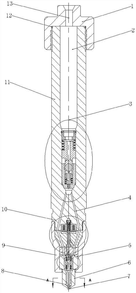
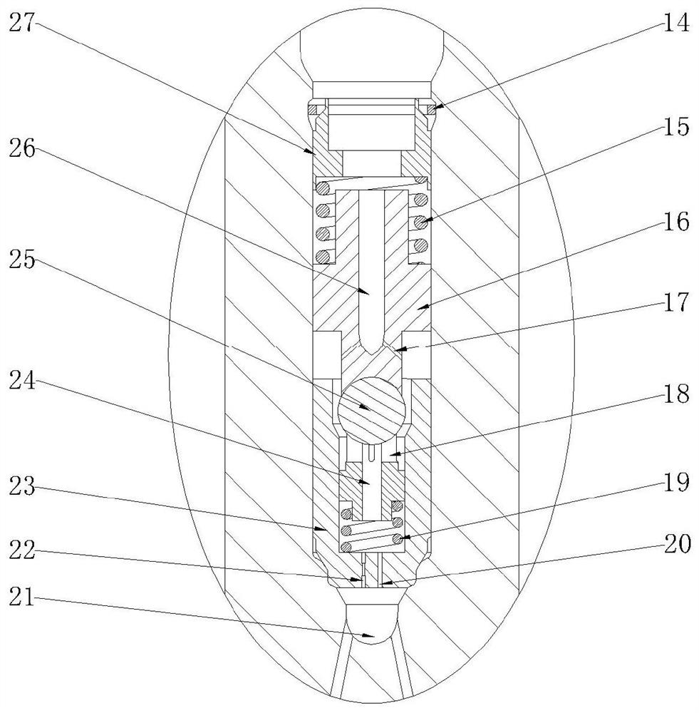
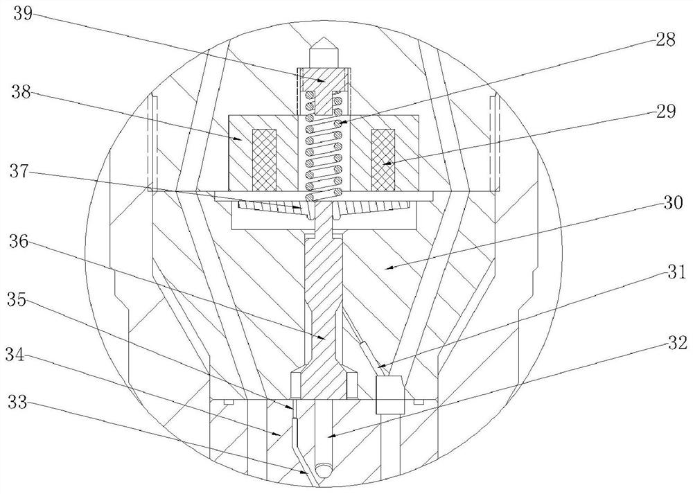
[0022] combine Figure 1-5 , the main structure of the dual-channel oil inlet resonance bypass type electronically controlled injector of the present invention includes an injector head 1, an injector body 11, a restrictor valve assembly 3, a solenoid valve assembly 10, a tight cap 9, and a needle valve assembly 5. , Nozzle 6. The fuel injector head 1 and the fuel injector body 11 are mated and connected through threads, and are sealed with a sealing ring 12 placed on the fuel injector body 11 . The main oil inlet hole 13 on the injector head 1 communicates with the pressure accumulating chamber 2 in the injector body 11 . Below the injector body 11 are the solenoid valve assembly 10 , the nozzle 6 and the needle valve assembly 5 , which are assembled and connected through the tight cap 9 . The restrictor valve assembly 3 is placed inside the injector body 11...


PUM


Abstract

The purpose of the present invention is to provide a dual-channel oil inlet resonance bypass type electronically controlled fuel injector, which includes an injector head, an injector body, a restrictor valve assembly, a solenoid valve assembly, a needle valve assembly, and a nozzle. The restrictor valve assembly is located inside the pressure accumulator chamber to ensure the stability of the fuel injection process of each cylinder under the condition of large fuel injection volume. A resonance through hole and a resonance throttle hole are processed at the bottom of the restrictor valve assembly, and the fluctuation of the fuel oil passing through the restrictor valve assembly is reduced by the principle of superposition of waves. A solenoid valve assembly and a needle valve assembly are arranged below. The solenoid valve adopts the form of a two-position three-way valve to reduce the dynamic oil return. A control slider is arranged inside the control chamber and contacts with the middle block, which slows down the fuel injection rate at the initial stage of injection and accelerates the seating response of the needle valve. The control chamber adopts the method of dual-channel oil feeding to further speed up the pressure build-up speed and realize the fast response characteristics of the injector. There is no static pressure difference inside the injector, and there is no static leakage of the injector.

Description

technical field [0001] The invention relates to an engine fuel injection device. Background technique [0002] The high-speed solenoid valve fuel injector realizes the complex fuel injection law with the help of the controller, which has the advantages of fast response, high control precision, flexible control strategy and reliable working performance. However, with the gradual increase of the fuel injection pressure in the current fuel injector, the performance of the fuel injector has also been tested in various aspects: the injector has static leakage without fuel injection; The dynamic oil return is large, which affects the fuel utilization rate; at the beginning of the injection, the fuel injection rate is too large, resulting in an increase in the emission of nitrogen oxides, and at the end of the injection, the control cavity is fed with oil in a single way, and the pressure build-up speed is slow, so that the fuel is not cut off quickly. , causing the emission of pa...

Claims


Application Information

Patent Timeline
Patent Type & Authority Patents(China)
IPC IPC(8): F02M51/06F02M61/10F02M61/16F02M61/20
CPCF02M51/061F02M61/10F02M61/16F02M61/205F02M2200/16
Inventor 刘秀琴范立云
Owner HARBIN ENG UNIV
Why Eureka
Try Eureka