Electromagnetic control pressure-storage and pressure-stabilizing oil sprayer

An electromagnetic control and fuel injector technology, which is applied in the direction of machines/engines, fuel injection devices, engine components, etc., can solve the fluctuation of fuel injection pressure and fuel injection rate, the increase of precise control of fuel injection volume, the pressure fluctuation of fuel injection system, etc. problems, achieve the effects of reducing pressure fluctuations, improving power and economy, and high control accuracy

Active Publication Date: 2014-09-03
无锡格迪斯机械制造有限公司
View PDF6 Cites 12 Cited by
  • Summary
  • Abstract
  • Description
  • Claims
  • Application Information

AI Technical Summary

Problems solved by technology

Although the electromagnetically controlled fuel injector has improved the emission performance of the diesel engine, there are still some shortcomings: because there is a control piston above the needle valve, it has a certain restrictive effect on further improving the response speed of the fuel injector; at the same time, due to the The turbulent flow will be intensified during the fuel injection and fuel cut-off of the injector, causing severe pressure fluctuations in the fuel injection system, causing large fluctuations in the fuel injection pressure and fuel injection rate, and increasing the precise control of the fuel injection volume. Difficulty

Method used


Image

  • Electromagnetic control pressure-storage and pressure-stabilizing oil sprayer
  • Electromagnetic control pressure-storage and pressure-stabilizing oil sprayer
  • Electromagnetic control pressure-storage and pressure-stabilizing oil sprayer

Examples


Embodiment Construction

[0014] The present invention is described in more detail below in conjunction with accompanying drawing example:

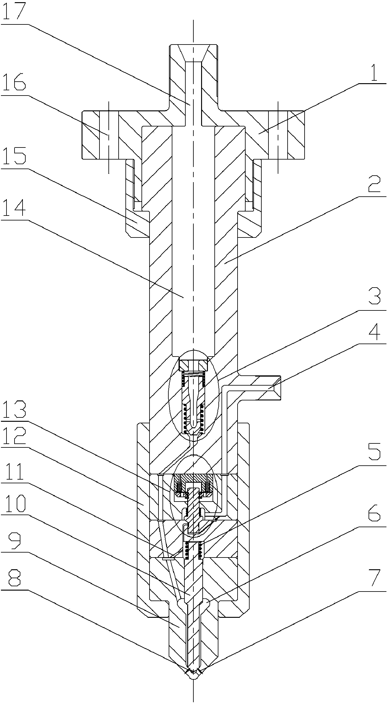
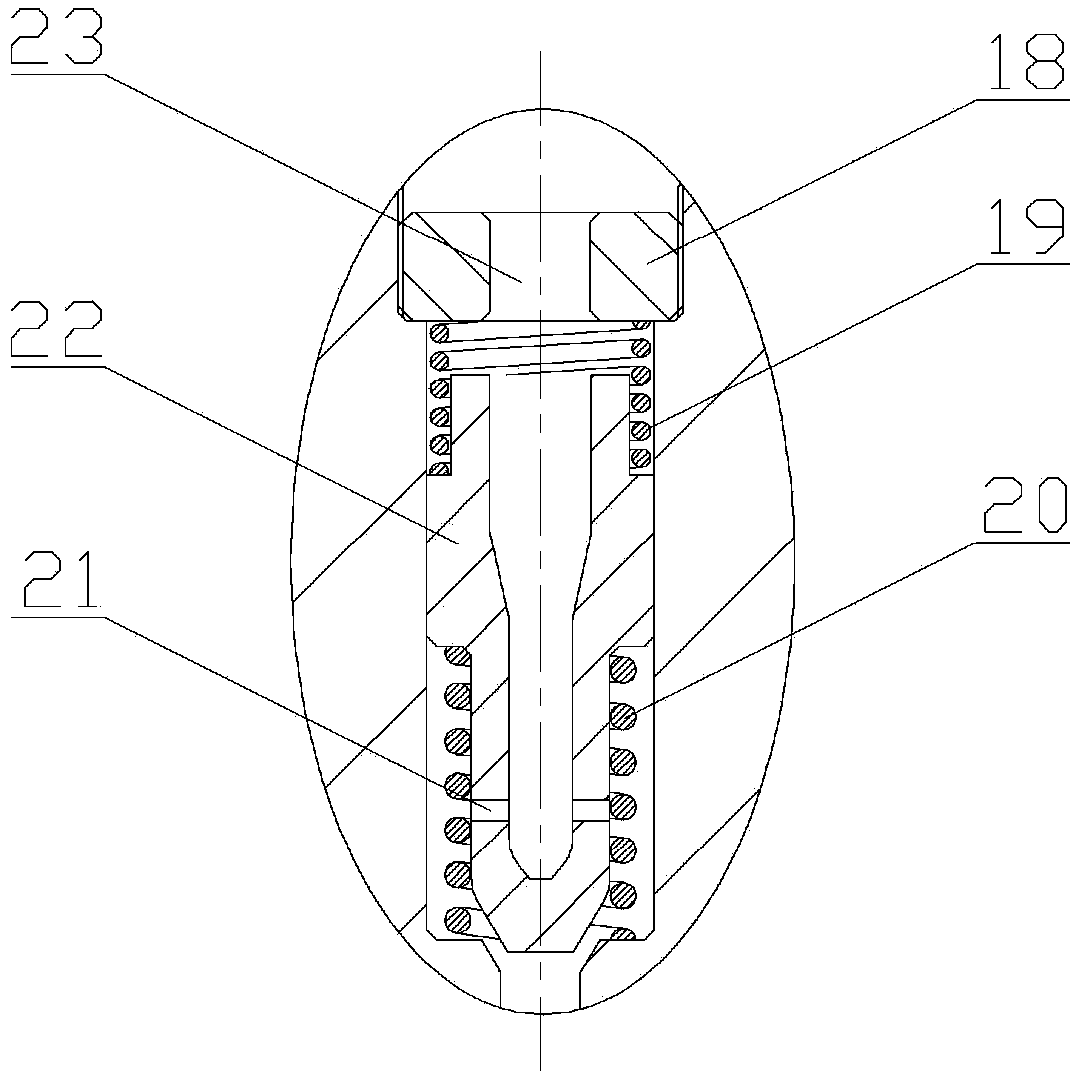
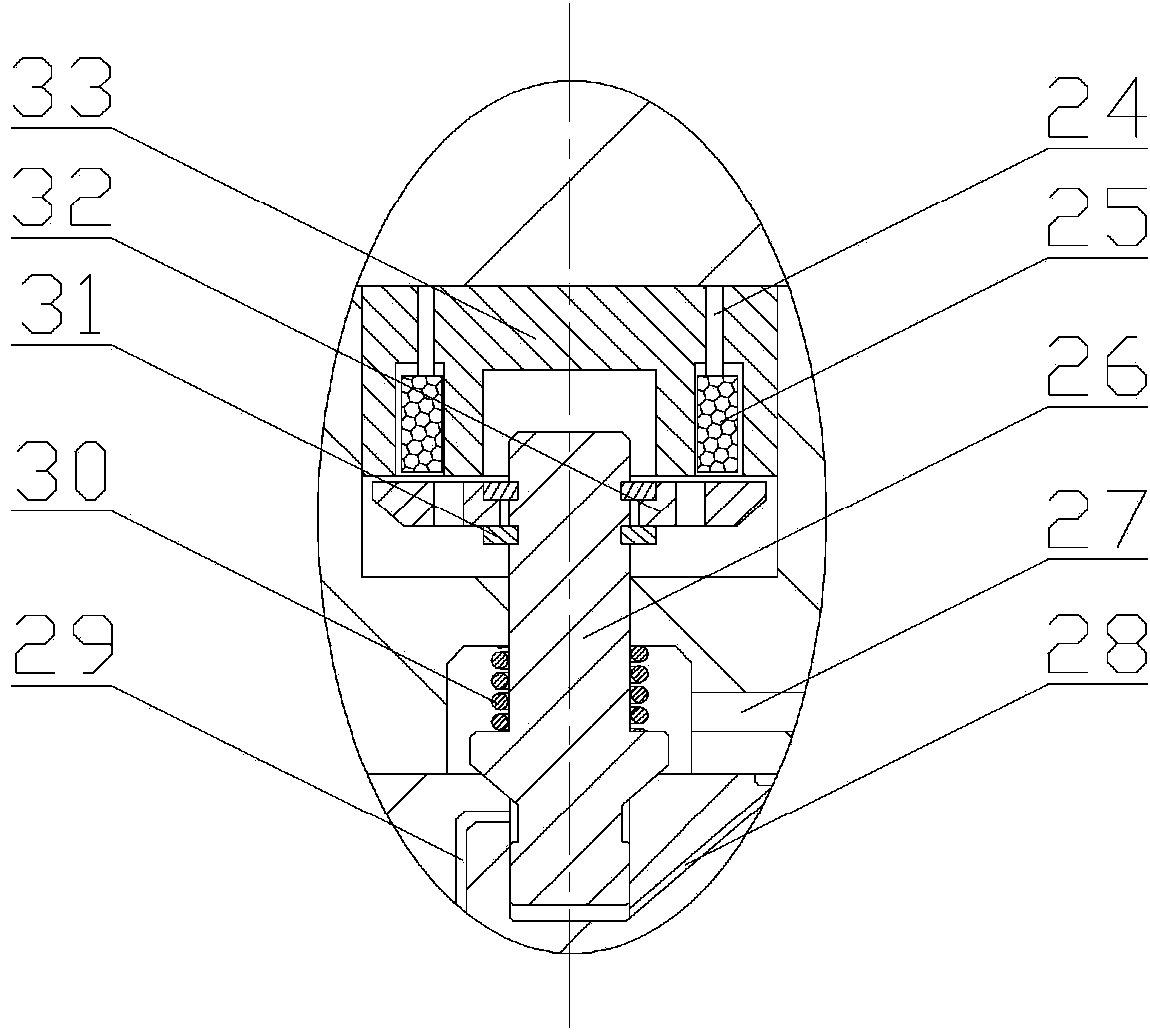
[0015] combine Figure 1~3 , the present invention is an electromagnetically controlled pressure accumulating and stabilizing fuel injector, which consists of a fuel injector head 1, a fuel injector body 2, a flow limiting assembly 3, a needle valve reset spring 5, a nozzle 9, a needle valve 10, a tight cap 12. The solenoid valve assembly 13 and the locking sleeve 15 are composed. The fuel injector body 2 is provided with a pressure accumulator chamber 14, and the pressure accumulator chamber 14 is respectively connected with the fuel inlet 17 opened on the injector head 1 and the main oil hole 23 opened on the limit block 18, and the flow is limited. The two ends of the piston 22 are respectively connected with the damping spring 19 and the return spring 20 of the flow-limiting piston. The flow-limiting piston 22 is provided with an orifice 21, and the needle va...


PUM


Abstract

The invention aims to provide an electromagnetic control pressure-storage and pressure-stabilizing oil sprayer. The oil sprayer comprises an oil sprayer head, an oil sprayer body, a flow limiting assembly, a needle valve reset spring, a spray nozzle, a needle valve, a cap nut, an electromagnetic valve assembly and a locking sleeve. The structure of the flow limiting assembly is adopted in the oil sprayer, therefore, fuel oil economy reduction caused due to the fact that the oil sprayer sprays oil abnormally and interruptedly can be effectively avoided and the working reliability of oil sprayer is guaranteed. A pressure storage cavity in the oil sprayer body can reduce pressure fluctuation caused in the fuel oil injection process and facilitate accurate control over oil spraying stability. Meanwhile, when the oil sprayer is used in a common rail fuel oil system, the structural size of a common rail pipe can be reduced, therefore, the requirements for strength of materials of the common rail pipe are reduced, the service life can be prolonged and the spatial utilization rate can be increased. The action process of the needle valve is directly driven by a solenoid valve, the response speed of the needle valve is high, the control precision is high, oil spraying is regular, flexible and changeable, the dynamic property and the economy of a diesel engine are effectively improved, and therefore the diesel engine can meet stricter emission regulations.

Description

technical field [0001] The invention relates to a fuel injector, specifically a diesel fuel injector. Background technique [0002] The traditional mechanically controlled fuel injector is mainly composed of injector body, nozzle, needle valve coupling, etc. It has the advantages of simple structure and high working reliability, but its fuel injection timing, fuel injection pressure and fuel injection rate are limited Due to the restriction of the cam shape of the high-pressure fuel supply pump, there are disadvantages such as inflexible fuel injection characteristics, slow response, and low precision in controlling the fuel injection quantity. With the increasingly stringent emission regulations, it is difficult to further improve the economy and emission performance of the engine. Also can not satisfy present market to the requirement of engine. [0003] Compared with the mechanically controlled injector, the electromagnetically controlled injector used in the electronica...

Claims


Application Information

Patent Timeline
Patent Type & Authority Applications(China)
IPC IPC(8): F02M51/06F02M61/10F02M61/16
Inventor 范立云白云扈爽马修真董晓露姚崇李文辉
Owner 无锡格迪斯机械制造有限公司
Why Eureka
Try Eureka