Piezo Controlled Accumulator and Regulator Fuel Injector

A fuel injector and voltage stabilizing technology, which is applied in the direction of machines/engines, fuel injection devices, engine components, etc., can solve problems such as the inability to meet the flexible control of fuel injection rate, the increase of precise control of fuel injection quantity, and the limitation of fuel injection times. , to achieve the effect of ensuring reliability and fuel economy, improving power and economy, and improving fuel injection stability

Active Publication Date: 2016-06-29
无锡格迪斯机械制造有限公司
View PDF6 Cites 0 Cited by
  • Summary
  • Abstract
  • Description
  • Claims
  • Application Information

AI Technical Summary

Problems solved by technology

Although the electromagnetically controlled fuel injector has improved the emission performance of the diesel engine, there are still some shortcomings: because there is a control piston above the needle valve, it has a certain restrictive effect on further improving the response speed of the fuel injector; at the same time, due to the The turbulent flow will be intensified during the fuel injection and fuel cut-off of the injector, causing severe pressure fluctuations in the fuel injection system, causing large fluctuations in the fuel injection pressure and fuel injection rate, and increasing the precise control of the fuel injection volume. Moreover, the structure of the electromagnetically controlled fuel injector is complicated. Due to the inductance of the solenoid valve coil, there is a certain lag time in its response, which leads to the limitation of further increasing the number of fuel injections and the repeatability of fuel injection needs to be improved. These The shortcomings make the existing electromagnetic control injector unable to meet higher requirements such as flexible control of injection rate

Method used


Image

  • Piezo Controlled Accumulator and Regulator Fuel Injector
  • Piezo Controlled Accumulator and Regulator Fuel Injector
  • Piezo Controlled Accumulator and Regulator Fuel Injector

Examples


Embodiment Construction

[0014] The present invention is described in more detail below in conjunction with accompanying drawing example:

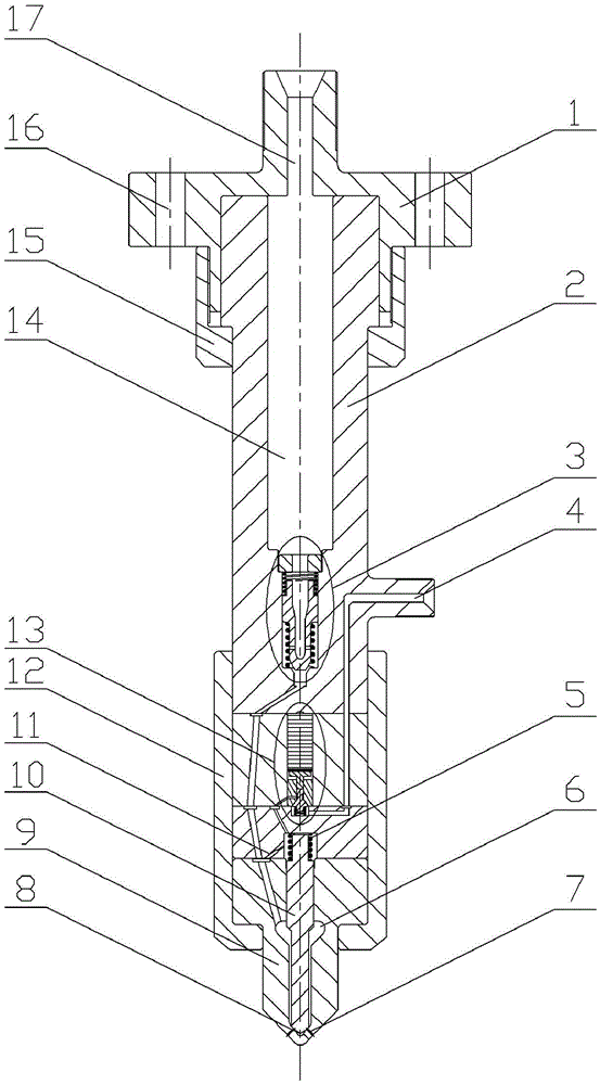
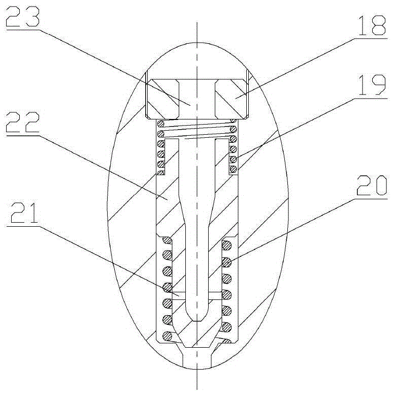
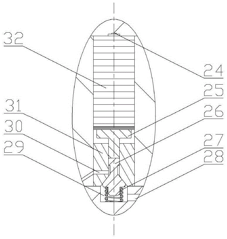
[0015] combine Figure 1 ~ Figure 3 , the present invention is a piezoelectric control accumulator pressure stabilizing fuel injector, which consists of a fuel injector head 1, a fuel injector body 2, a current limiting assembly 3, a needle valve return spring 5, a nozzle 9, a needle valve 10, a tight The cap 12, the piezoelectric control assembly 13 and the locking sleeve 15 are composed. The fuel injector body 2 is provided with a pressure accumulator chamber 14, and the pressure accumulator chamber 14 is respectively connected with the fuel inlet 17 opened on the injector head 1 and the main oil hole 23 opened on the limit block 18, and the flow is limited. The two ends of the piston 22 are respectively connected with the damping spring 19 and the return spring 20 of the flow-limiting piston. The flow-limiting piston 22 is provided with an orifice 21, and the ...


PUM


Abstract

The object of the present invention is to provide a piezoelectric control accumulator pressure stabilized fuel injector, including a fuel injector head, a fuel injector body, a flow limiting assembly, a needle valve return spring, a nozzle, a needle valve, a tight cap, and a piezoelectric control assembly and locking sleeves. The current limiting component structure can effectively avoid the fuel economy decline caused by the abnormal continuous injection of the injector, and ensure the reliability of the injector; the pressure storage chamber in the injector body can reduce the fuel injection process The resulting pressure fluctuation is beneficial to the precise control of fuel injection stability. When the invention is used in a common rail fuel system, it can reduce the structural size of the common rail pipe, thereby reducing the material strength requirements of the common rail pipe and improving its service life. and space utilization; the action process of the needle valve is directly driven by the piezoelectric stack, the needle valve responds quickly, the control degree of freedom is large, and the fuel injection law is flexible and changeable, which effectively improves the power and fuel economy of the diesel engine, making the diesel engine Ability to meet stricter emissions regulations.

Description

technical field [0001] The invention relates to a fuel injector, specifically a diesel fuel injector. Background technique [0002] The traditional mechanically controlled fuel injector is mainly composed of injector body, nozzle, needle valve coupling, etc. It has the advantages of simple structure and high working reliability, but its fuel injection timing, fuel injection pressure and fuel injection rate are limited Due to the restriction of the cam shape of the high-pressure fuel supply pump, there are inflexible fuel injection characteristics, slow response, and poor control accuracy of the fuel injection quantity. With the increasingly stringent emission regulations, it is difficult to further improve the economy and emission performance of the engine. Also can not satisfy present market to the requirement of engine. [0003] Compared with the mechanically controlled injector, the electromagnetically controlled injector used in the electronically controlled fuel inject...

Claims


Application Information

Patent Timeline
Patent Type & Authority Patents(China)
IPC IPC(8): F02M61/10
Inventor 白云范立云刘洋扈爽刘鹏马修真李学民赵建辉
Owner 无锡格迪斯机械制造有限公司
Why Eureka
Try Eureka