

Marine propulsion device
- Summary
- Abstract
- Description
- Claims
- Application Information
AI Technical Summary
Benefits of technology
Problems solved by technology
Method used
Image

Examples
Embodiment Construction
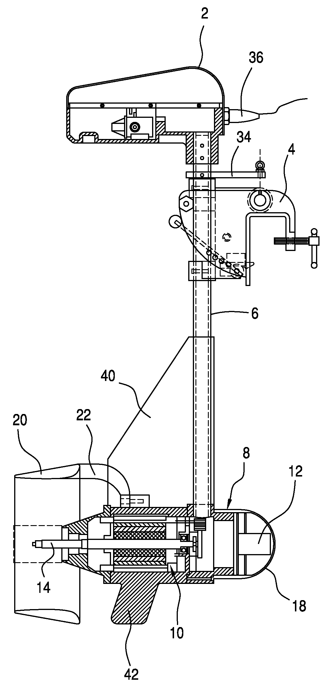
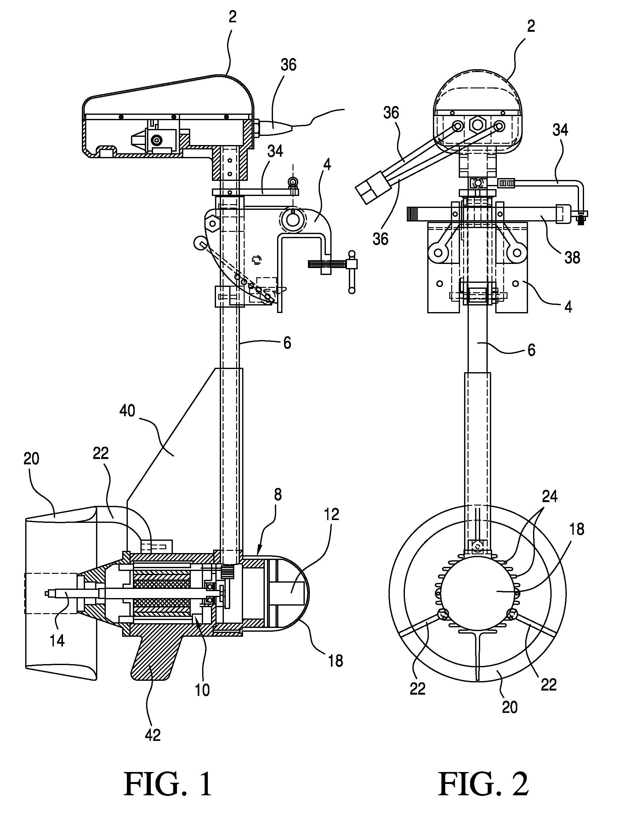
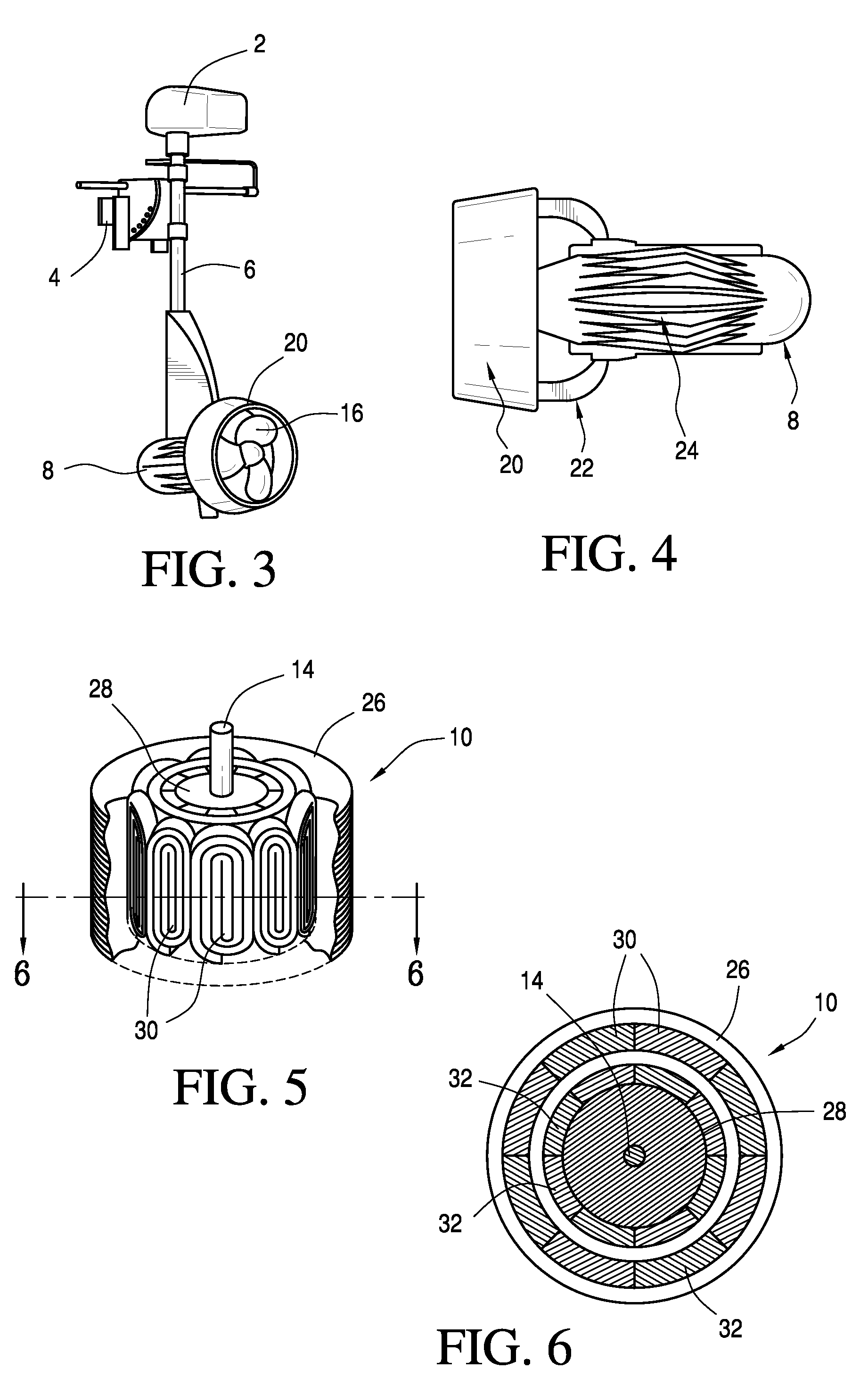
[0014]The marine propulsion system according to the invention will first be described with reference to FIGS. 1-3. As shown therein, the system includes a control assembly 2, a bracket 4 for mounting the system to a vessel such as the transom of a boat, a shaft 6 connected with the mounting bracket, and a submersible housing 8. Within the housing is mounted a brushless electric motor 10 and a variable voltage controller 12 for the motor. The motor has a drive shaft 14 which extends from the housing along a longitudinal axis thereof, and a propeller 16 is connected directly with the drive shaft. No transfer linkage is required between the motor and the propeller.
[0015]The housing has a curved nose portion 18 at the forward end in the direction of travel so that the housing passes smoothly through the water and sheds debris. Rearwardly, the housing includes a nozzle 20 which preferably has a truncated conical configuration and surrounds the propeller as shown in FIGS. 1 and 3. The noz...
PUM
 Abstract
Description
Claims
Application Information