

Air stream collecting device, wind motor and wind energy collecting device
A technology of a wind engine and a collection device, which is applied to wind engines, wind engines consistent with the wind direction, control of wind engines, etc., and can solve problems such as difficulty in preventing typhoons or super-strong wind safety hazards, etc.
- Summary
- Abstract
- Description
- Claims
- Application Information
AI Technical Summary
Problems solved by technology
Method used
Image

Examples
Embodiment 1
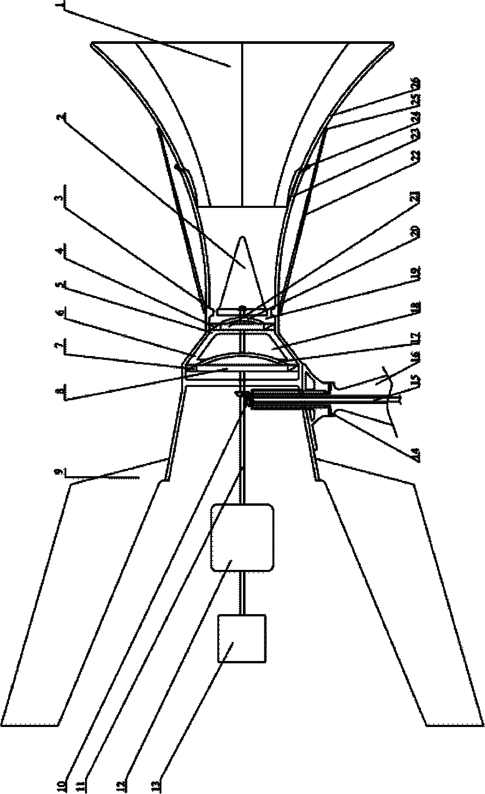
[0033] A wind energy harvesting device such as Figure 1-4 As shown, a wind turbine, a gas compression device 12 and an air storage tank 13 are included. A wind turbine includes an airflow collection device and engine components. in:
[0034] The airflow collecting device includes an airflow collecting channel 1 with a large outer opening and a small inner opening, a deflector 2 , a wind direction positioning wing 9 and a support seat 12 . A guide body 2 is arranged in the air flow collection channel 1, and the guide body 2 is fixed on the central axis of the air flow collection channel 1 near the inner mouth. The guide body 2 is basically a cone extending from the inner port along the direction of the outer port. An annular air flow passage 3 is formed between 1 and the conical guide body 2 . A wind direction positioning wing 9 is fixed on the outer casing at the tail end of the airflow collecting channel 1 . The support seat 12 is installed below the air flow collection ...
Embodiment 2
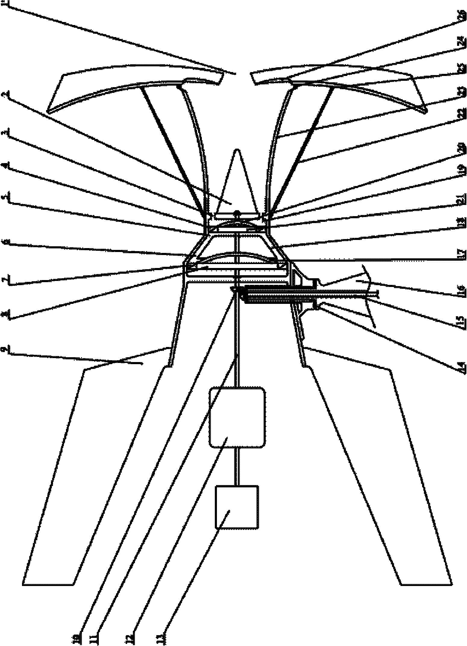
[0041] Another wind energy harvesting device, such as Figure 5 and Image 6 As shown, this embodiment is the same as the first embodiment except that the structure of the movable part on the channel wall of the airflow collecting channel 1 is different from the first embodiment.
[0042] In this implementation, a rotatable panel 22 and an elastic support 23 are provided on the channel wall 24 of the airflow collection channel 1 , one end of the rotatable panel 22 is hinged to the channel wall 24 , and the rotatable panel 22 is supported by the elastic support 23 . When the wind force does not exceed the preset value, the rotatable panel 22 remains closed to the channel wall 24 under the action of the elastic force of the elastic support member 23 . When the wind force exceeds the preset value, under the action of the elastic support 23, the rotatable panel 22 is opened under pressure, releasing part of the airflow exceeding the preset value to the outside of the airflow coll...
Embodiment 3
[0044] A wind power generator, such as Figure 7 and Figure 8 shown, including wind turbines and generators. A wind turbine includes an airflow collection device and engine components. The airflow collecting device includes an airflow collecting channel 1 with a large outer opening and a small inner opening, a deflector 2 , a wind direction positioning wing 9 and a support base 12 . In this embodiment, the structure of the engine assembly is the same as the first embodiment. In the airflow collecting device, except that the structure of the movable part of the channel wall 23 of the airflow collecting channel 1 is different from the first embodiment, other structures of the airflow collecting device are the same as the first embodiment. The power generated by the bipolar impellers (21, 8) is output by the power output shaft 11 and connected to the generator 12.
[0045] In this embodiment, the movable part provided on the channel wall 23 of the airflow collection channel ...
PUM
 Abstract
Description
Claims
Application Information