Worm wheel

A worm gear and gear tooth technology, applied in the field of transmission, can solve the problems of being unsuitable for the installation and use of high-precision instruments, and the volume of the transmission is large, and achieve the effects of light weight, improved transmission efficiency, and large torque output.

Inactive Publication Date: 2019-07-26
赵若君
View PDF18 Cites 2 Cited by
  • Summary
  • Abstract
  • Description
  • Claims
  • Application Information

AI Technical Summary

Problems solved by technology

Although this method reduces the volume of the transmission device in the lateral direction, the volume of the transmission device in the axial direction of the worm is still relatively large, which is not suitable for installation and use in high-precision instruments

Method used


Image

  • Worm wheel
  • Worm wheel
  • Worm wheel

Examples


Embodiment Construction

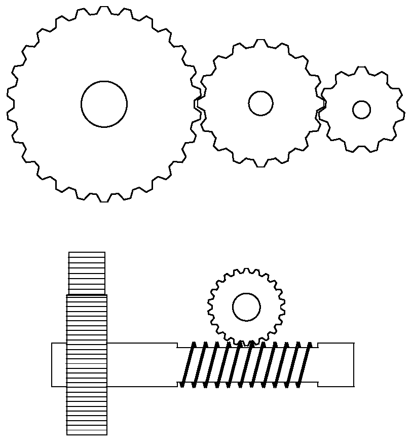
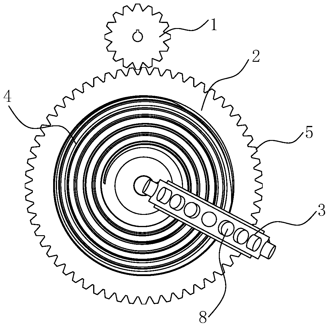
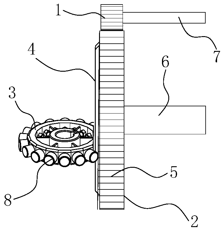
[0027] combine Figure 2-8 A new type of face transmission device with two-stage reduction function is shown, including pinion 1, transmission wheel 2 and worm wheel 3. The pinion 1 is connected with the power input shaft 7 for inputting power to the device. The worm gear 3 is connected with the power output shaft for outputting decelerated power. combine figure 2 and 3 As shown, the middle part of one end surface of the transmission wheel 2 is provided with a helical tooth 4 , the end surface of the worm wheel 3 is perpendicular to the end surface of the transmission wheel 2 , and the worm wheel 3 meshes with the helical tooth 4 . A circle of first gear teeth 5 is arranged on the peripheral surface of the transmission wheel 2 , and the first gear teeth 5 can be formed by machining, of course, can also be formed by direct die forging. The pinion 1 meshes with the first gear teeth 5, and the pinion gear 1 and the first gear teeth 5 realize the first deceleration during tra...


PUM


Abstract

The invention relates to the field of driving devices, and particularly provides a worm wheel. The worm wheel comprises a wheel body and second gear teeth, wherein the second wheel teeth are arrangedon the circumferential face of the wheel body, the second wheel teeth are cylinders extending along the radial directions of the worm wheel, and sliding friction or rolling friction is formed betweenthe second wheel teeth and spiral teeth; the wheel body comprises an outer wheel ring and an inner wheel ring, and the inner wheel ring and the outer wheel ring are connected through a plurality of spokes uniformly distributed around the center of the wheel body; a shaft hole is formed in the center of the inner wheel ring, and the second wheel teeth are arranged on the surface of the outer wheelring. The worm wheel is small in size, compact in structure, and can realize large-driving-ratio drive and large-torque output; and the worm wheel has the both advantages of gear drive and worm drive,and is simple in structure, low in manufacturing cost and convenient to popularize and popularize.

Description

[0001] The present invention is a divisional application for the protection of different improvement points of the invention patent named: a new type of end face transmission device with two-stage deceleration function, application number: 201710767551.4, application date: 2017-08-31. technical field [0002] The invention relates to the field of transmission devices, in particular to a worm wheel for end face transmission devices. Background technique [0003] At present, the two-stage reduction transmission device adopted in the prior art includes: a combination of multiple gears or a gear set plus a worm gear set. Such as figure 1 As shown, the method of combining multiple gears usually includes three gears, large, medium and small, and the three gears mesh in turn to realize two-stage reduction transmission. Although the principle structure is relatively simple, this method is usually bulky and due to two The large inter-tooth clearance of the set of meshing teeth leads...

Claims


Application Information

Patent Timeline
Patent Type & Authority Applications(China)
IPC IPC(8): F16H1/20F16H1/24F16H55/08F16H55/10F16H57/04
CPCF16H1/203F16H1/24F16H55/08F16H55/10F16H57/043
Inventor 赵若君陈守安
Owner 赵若君
Why Eureka
Try Eureka