Double-frequency high-gain dielectric resonant array antenna

A medium resonance, array antenna technology, applied in the direction of antenna, antenna coupling, antenna array, etc., can solve the problem of increasing the weight and size of the antenna, and achieve the effect of suppressing edge diffraction, novel ideas, and easy mass production.

Active Publication Date: 2017-04-26
TONGYU COMM INC
View PDF8 Cites 8 Cited by
  • Summary
  • Abstract
  • Description
  • Claims
  • Application Information

AI Technical Summary

Problems solved by technology

In this way, the weight and size of the antenna will be further increased

Method used


Image

  • Double-frequency high-gain dielectric resonant array antenna
  • Double-frequency high-gain dielectric resonant array antenna
  • Double-frequency high-gain dielectric resonant array antenna

Examples


Embodiment Construction

[0058] The preferred embodiments of the present invention are given below in conjunction with the accompanying drawings to describe the technical solution of the present invention in detail. It should be noted that the preferred embodiments described here are only used to illustrate and explain the present invention, and are not used to limit or limit the present invention.

[0059] see Figure 1-15 , the design method of the dual-frequency high-gain dielectric resonant array antenna of the present invention comprises the following steps:

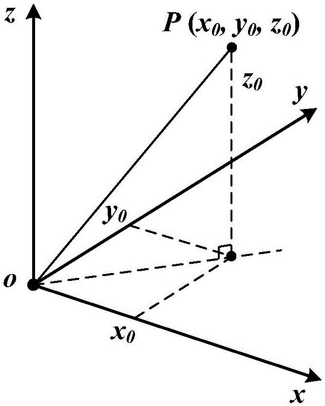
[0060] Step 1, establish a space Cartesian coordinate system, see figure 1 ;

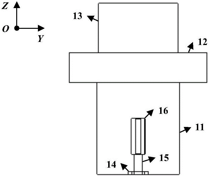
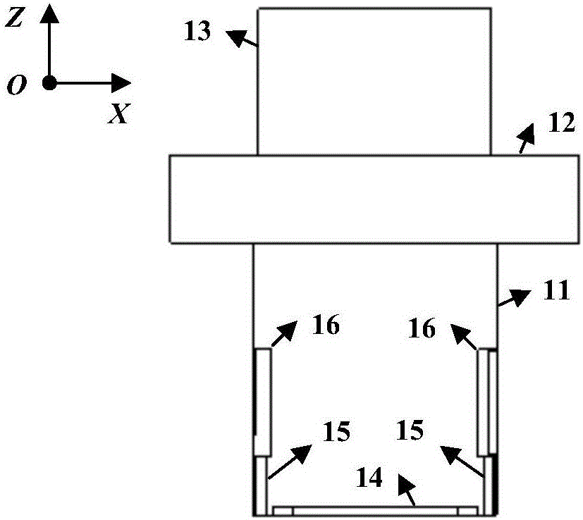
[0061] Step 2. Construct the dielectric resonance unit: on the XOY plane, construct three dielectric cubes stacked up and down and with the centers coincident, as shown in the figure Figure 2-5 In the upper cube 13, the middle cube 12, and the lower cube 11, specifically, first draw a side length L with the coordinate origin O as the center 1 square, and the...


PUM


Abstract

The invention provides a double-frequency high-gain dielectric resonance array antenna. The antenna comprises a substrate, two microstrip feed networks and a dielectric resonant unit array composed of N dielectric resonant units, N >=1, the microstrip feed networks are arranged on the substrate, the N dielectric resonant units are arranged on the substrate in a coaxial or collinear arrangement manner, feed points of the dielectric resonant units are coupled to the output ends of the two microstrip feed networks, first feed slots are arranged in two side surfaces of each dielectric resonant unit, and a second feed slot is arranged in the bottom surface of each dielectric resonant unit. One microstrip feed network is provided with a group of coupling apertures close to the output end of a dielectric cube, the other microstrip feed network is provided with a group of coupling probes close to the output end of a dielectric cube, the coupling probes and the first feed slots form a coupling power, the coupling apertures are formed in the substrate and coupled with the second feed slots. The high-gain dielectric resonance array antenna is compact in structure, low in weight, low in loss, high in efficiency, low in cost, easy to assemble and suitable for batch production and includes fewer welding points, and can be used to provide effective or beneficial references for design and improvement of other broadband, multi-frequency, low-gain dielectric resonant units or array antennas.

Description

[0001] 【Technical field】 [0002] The invention relates to a mobile communication base station antenna device and technology, in particular to a dual-band high-gain dielectric resonant array antenna and its technology. [0003] 【Background technique】 [0004] The base station antenna is the air interface between the user terminal of the mobile communication system and the system network, and its impact on the performance of the entire communication system is even more critical and decisive. In the long-term technological evolution, the base station antenna has formed the current mainstream technical solution that uses the die-casting vibrator as the basic radiating unit, selects the coaxial cable or printed wire to construct the feed network, and uses the pull-rod phase shifter to realize the electric downtilt. In the 2G / 3G / 4G frequency band (698-960 / 1710-2700MHz), the size of the vibrator is usually on the order of 30mm-150mm, and the die-casting process can meet its precision...

Claims


Application Information

Patent Timeline
Patent Type & Authority Applications(China)
IPC IPC(8): H01Q1/36H01Q1/48H01Q1/52H01Q19/10H01Q21/00H01Q21/08H01Q21/24H01Q5/20H01Q5/10
CPCH01Q1/36H01Q1/48H01Q1/523H01Q5/10H01Q5/20H01Q19/106H01Q21/0006H01Q21/0075H01Q21/08H01Q21/24
Inventor 李道铁谭想吴中林刘木林
Owner TONGYU COMM INC
Why Eureka
Try Eureka