
Multifunctional adapter used in automatic wine vending machines
A technology for converting joints and wine vending machines, which is applied in packaging, liquid distribution, transportation and packaging, etc., can solve the problems affecting the health of consumers, the retention of wine, and attracting mosquitoes, etc., to ensure food hygiene and safety and reduce residues. The amount of alcohol, the effect of easy rinsing and cleaning
- Summary
- Abstract
- Description
- Claims
- Application Information
AI Technical Summary
Problems solved by technology
Method used
Image

Examples
Embodiment 1
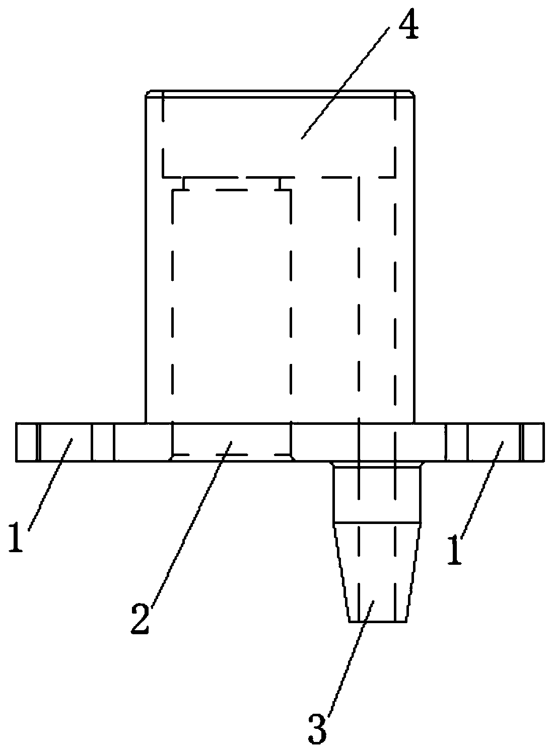
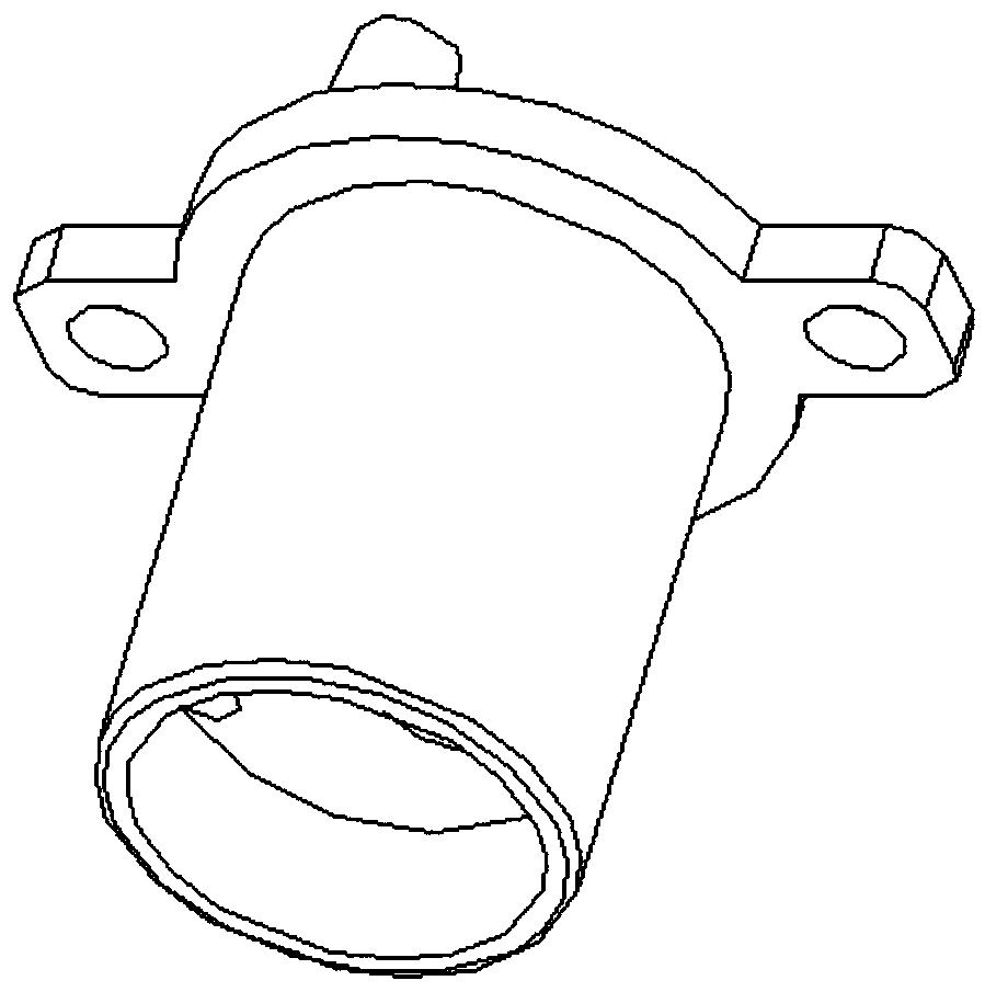
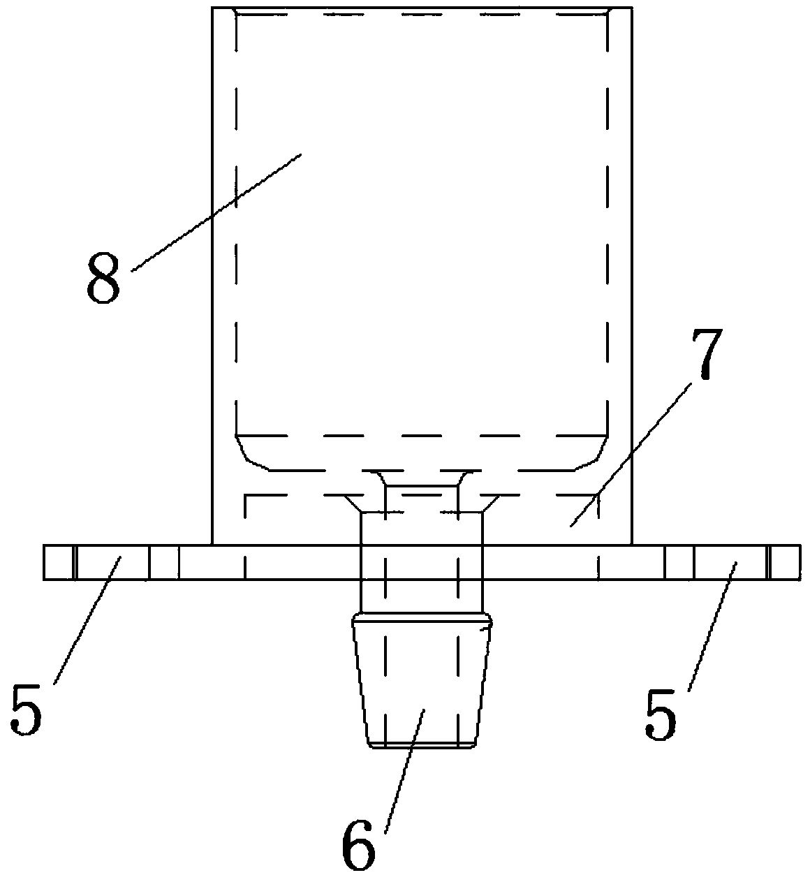
[0018] This embodiment provides a multifunctional conversion joint used in automatic wine vending machines, including: an upper joint and a lower joint; the upper joint includes: an upper hose hole 2, a vent hole 3, an upper installation hole 1 and an upper joint Groove 4, the vent hole 3 is a raised structure, the upper mounting hole 1 is located on both sides of the end face of the upper joint, the vent hole 3, the upper hose hole 2 communicate with the upper groove 4, and the upper groove 4 placed at the bottom of the upper joint; the lower joint includes: a barrel body 8, a lower groove 7, a lower installation hole 5, and a lower hose hole 6; one end of the lower joint is provided with a lower groove 7, and the lower The holes 5 are arranged on both sides of the end face, the lower hose hole 6 passes through the groove to form a convex structure, and the lower hose hole 6 communicates with the barrel body 8; the upper joint is sleeved inside the barrel body 8 of the lower j...
PUM
 Abstract
Description
Claims
Application Information