A kind of oil and gas separation air conditioner compressor

A separate technology for air-conditioning compressors, applied in the field of air-conditioning compressors, can solve the problems of increasing rotor rotation damping, reducing system efficiency, and occupancy

Active Publication Date: 2018-08-28
钱建忠
View PDF6 Cites 0 Cited by
  • Summary
  • Abstract
  • Description
  • Claims
  • Application Information

AI Technical Summary

Problems solved by technology

[0005] Although the rotary compressor adopts the above-mentioned second lubrication method to solve the problem of lubrication and sealing between the outer peripheral surface of the rotary sleeve and the inner wall of the cylinder body, it also has the following disadvantages when used in air conditioners: (1). The cylinder of the compressor occupies the volume of the basic unit of the compressor cavity. Since the volume of the compressor unit is fixed, relatively speaking, the space occupied by the refrigerant is correspondingly reduced. For the same compressor, its refrigerant displacement is Reduce; the higher the temperature of the compressor, the faster the vaporization of the lubricating oil, the larger the space occupied, and the more lubricating oil is taken away into the pipeline; (2), the lubricating oil is viscous, and the compressor is working , the presence of lubricating oil will virtually increase the damping of rotor rotation, thereby increasing the power consumption of the compressor; (3), lubricating oil and refrigerant mix and flow in the air conditioner pipeline, which will cause the lubricating oil to adhere to The inner wall of the copper tube forms an oil film insulation layer, and the refrigerant needs to pass through the oil film insulation layer to exchange heat, so it will greatly affect the heat exchange of the refrigerant, thereby reducing the efficiency of the entire system

Method used


Image

  • A kind of oil and gas separation air conditioner compressor
  • A kind of oil and gas separation air conditioner compressor
  • A kind of oil and gas separation air conditioner compressor

Examples


Embodiment

[0055] Example: an oil-gas separation type air conditioner compressor

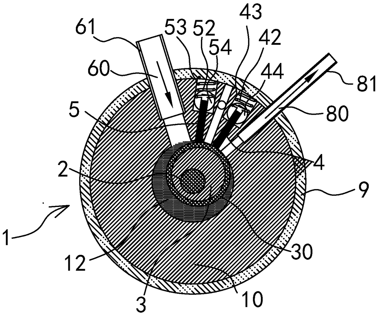
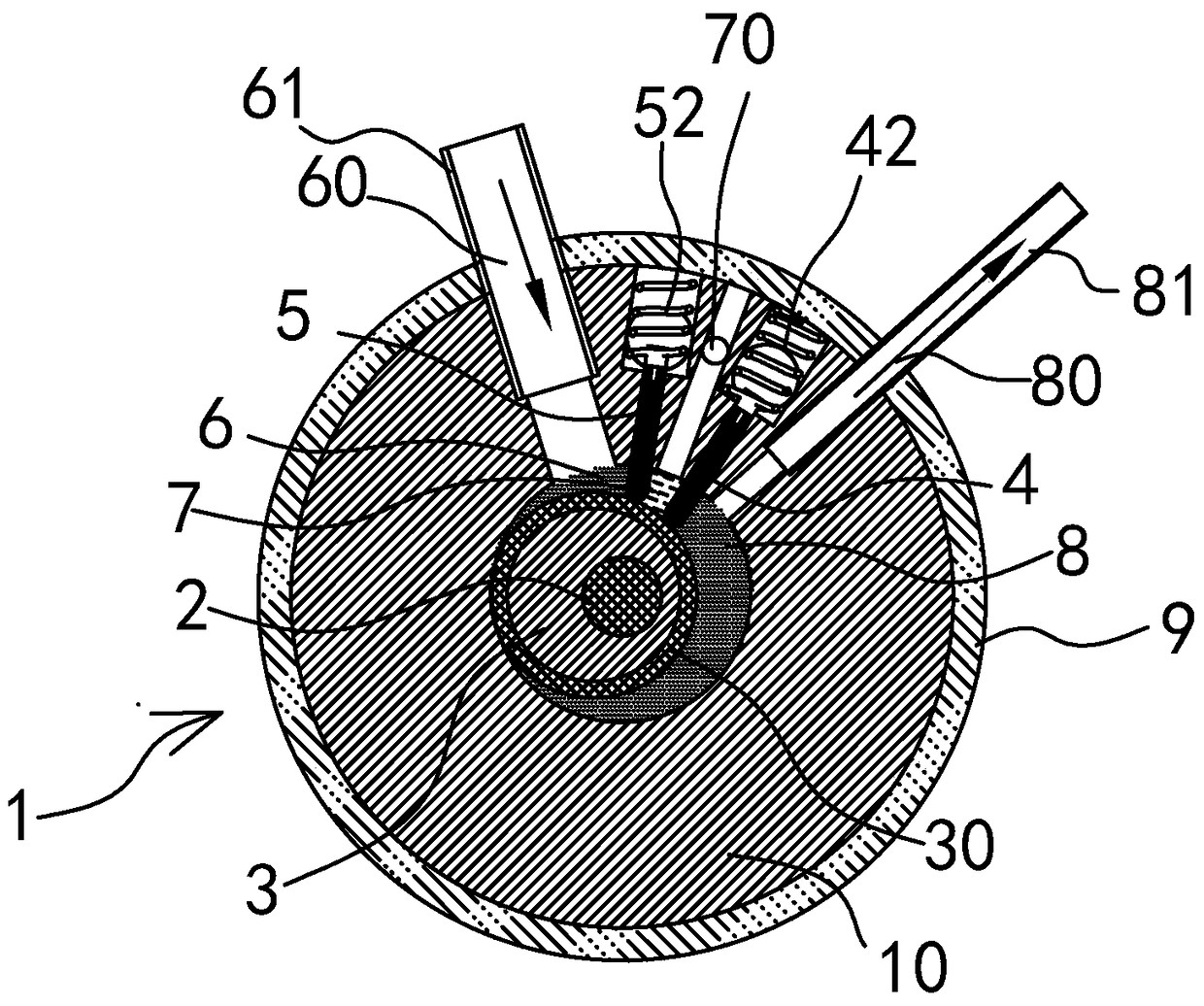
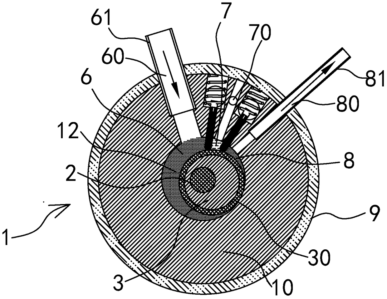
[0056] See attached Figure 1~3 , attached Figure 5 , an oil-gas separation type air conditioner compressor, including a shell 9, the shell 9 includes: a drive motor, a cylinder 1, a main shaft 2, an eccentric rotor 3, a rotary sleeve 30, a first sliding assembly and a second sliding assembly.

[0057] The main shaft 2 is concentric with the cylinder body 1, and the eccentric rotor 3 is arranged on the outer peripheral surface of the main shaft 2 and is eccentric with the main shaft 2. The output shaft of the driving motor is connected to the main shaft 2 to drive the main shaft 2 to rotate.

[0058] Wherein, the cylinder 1 includes a cylinder body 10 and sealing end caps 11 arranged on the upper and lower ends of the cylinder body 10, the cylinder body 10 and the sealing end caps 11 enclose the entire cylinder space. The lubricating oil storage space 71 is formed between the shell 9 and the cylinder b...


PUM


Abstract

The invention relates to an oil-gas separation type air-condition compressor. The oil-gas separation type air-condition compressor comprises a casing, a cylinder body, a spindle, an eccentric rotor, a rotary sleeve, a first sliding baffle plate and a second sliding baffle plate, wherein the first sliding baffle plate penetrates into a first sliding chute to be in sliding fit with the first sliding chute; the second sliding baffle plate penetrates into a second sliding chute to be in sliding fit with the second sliding chute; a working crescent cavity is divided by the first sliding baffle plate and the second sliding baffle plate into a suction cavity, a lubricating oil cavity and a discharge cavity which do not communicate with one another. With the adoption of the oil-gas separation type air-condition compressor, separation of lubricating oil and a refrigerant is realized, that is, independent lubrication and sealing of the lubricating oil are realized, the area, occupied by the lubricating oil, of the work crescent cavity is reduced, and space occupied by the refrigerant is relatively increased, so that compressor discharge rate is increased. When the air-condition compressor is applied to an air conditioner, viscous resistance of the lubricating oil to the eccentric rotor is avoided, power consumption of the compressor is greatly reduced accordingly, and no lubricating oil is attached to the inner wall of a copper pipe, so that heat exchange is enhanced. The oil-gas separation type air-condition compressor is simple in structure, low in cost and good in effect.

Description

technical field [0001] The invention belongs to the field of air-conditioning compressors, and in particular relates to a rotor-type oil-gas separation type air-conditioning compressor, which can be applied not only to single-rotor compressors, but also to multi-rotor compressors. Background technique [0002] The rotary compressor is a volumetric rotary compressor. The change of the working volume of the cylinder is realized by the rotation of an eccentric device in the cylinder. The cylinder body is composed of a cylinder body and a sealing end cover. The eccentric device includes a main shaft, an eccentric rotor and a rotary sleeve. The main shaft and the eccentric rotor are integrally formed, and the rotary sleeve is sleeved on the outer periphery of the eccentric rotor to form the eccentric device. In the working state, the eccentric device inscribes with the cylinder body and always rolls along the inner wall of the cylinder body to form a working crescent cavity. Th...

Claims


Application Information

Patent Timeline
Patent Type & Authority Patents(China)
IPC IPC(8): F04C18/344F04C29/02F04C29/12
Inventor 钱建忠
Owner 钱建忠
Why Eureka
Try Eureka