Rapidly positioned column foot anchor bolt structure

An anchor bolt, fast technology, applied in the direction of building construction, building material processing, construction, etc., can solve the problems of slow speed and low efficiency, and achieve the effects of strong structure, improved engineering quality, and stable and reliable structure

Pending Publication Date: 2017-06-06
CHINA MCC5 GROUP CORP
View PDF7 Cites 1 Cited by
  • Summary
  • Abstract
  • Description
  • Claims
  • Application Information

AI Technical Summary

Problems solved by technology

[0003] The purpose of the present invention is to provide a column foot anchor bolt structure in place quickly, to solve the problems of slow speed and low efficiency in the positioning construction of the steel column foot in the prior art, and to simplify the on-site construction process during the positioning of the steel column foot. The purpose of improving construction efficiency

Method used


Image

  • Rapidly positioned column foot anchor bolt structure
  • Rapidly positioned column foot anchor bolt structure

Examples


Embodiment 1

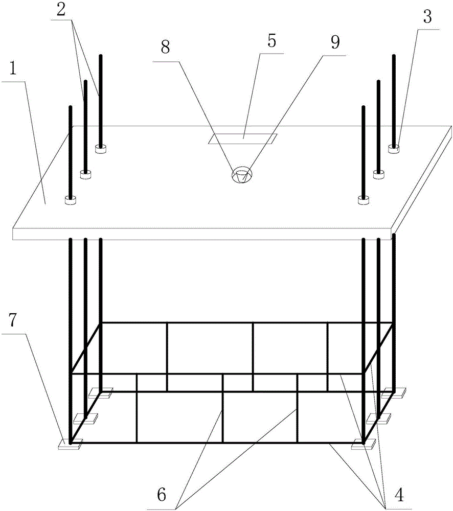
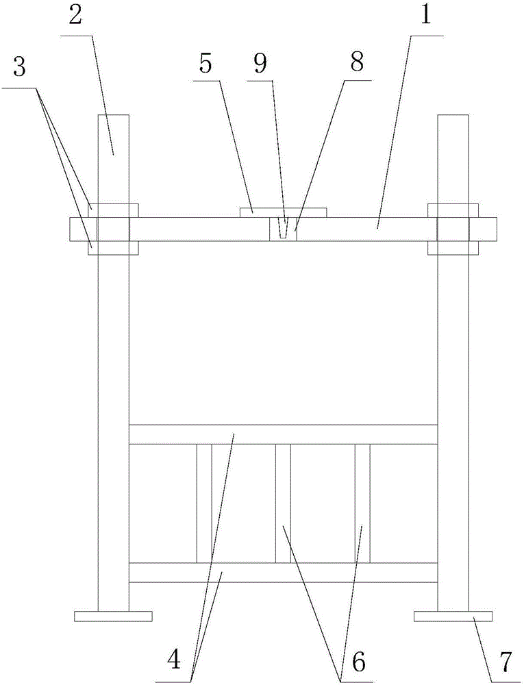
[0026] Such as figure 1 and figure 2 A fast-positioning column foot anchor bolt structure shown includes a positioning template 1, anchor bolt holes are set on the positioning template 1, anchor bolts 2 are inserted into the anchor bolt holes, and the positioning template 1 is fixed to the anchor bolt 2 by nuts 3 , the axes of each anchor bolt 2 are parallel, and two adjacent anchor bolts 2 are fixedly connected with two transverse ribs 4 distributed up and down along the axis direction of the anchor bolt 2, and all transverse ribs 4 are located on the lower side of the positioning template 1, and The transverse rib 4 is perpendicular to the axis of the anchor bolt 2; the vertical rib 6 is fixedly connected between the upper and lower adjacent two transverse ribs 4; the upper surface of the positioning template 1 is provided with a level 5; the center of the positioning template 1 is provided with a through hole 8. The beam emitting device 9, the emitting end of the beam emi...


PUM


Abstract

The invention discloses a rapidly positioned column foot anchor bolt structure which comprises a positioning mold plate, wherein anchor bolt holes are formed in the positioning mold plate; anchor bolts are inserted into the anchor bolt holes; the positioning mold plate is fixed with the anchor bolts through screw nuts; the axes of the anchor bolts are parallel to one another; N transverse ribs which are distributed up and down in the direction of the axes of the anchor bolts are fixedly connected between the every two adjacent anchor bolts; the transverse ribs are all positioned on the lower side of the positioning mold plate; the transverse ribs are perpendicular to the axes of the anchor bolts; longitudinal ribs are fixedly connected between every two adjacent transverse ribs up and down; a gradienter is arranged on the upper surface of the positioning mold plate; a through hole is formed in the center of the positioning mold plate; a light beam emission device is arranged on the positioning mold plate; the emitting end of the light beam emission device is positioned inside the through hole; light beams are emitted to the lower side of the positioning mold plate; and the emitted light beams are parallel to the axes of the anchor bolts. By adopting the rapidly positioned column foot anchor bolt structure, the problems that in the prior art, a steel column foot is low in positioning construction speed and low in efficiency can be solved, and the purposes that on-site construction procedures of steel column foot positioning are simplified and the construction efficiency is improved can be achieved.

Description

technical field [0001] The invention relates to the field of steel structure building construction, in particular to a column base anchor bolt structure that can be quickly placed in place. Background technique [0002] With the continuous promotion of steel structure buildings, the scale of various steel structure construction projects is increasing day by day, and projects such as steel structure industrial plants, steel structure residences, high-rise steel structures, and steel structure venues are increasing. In steel structure buildings, steel column feet generally adopt flat column feet connected by anchor bolts. The anchor bolt is a key part connecting the foundation and the superstructure, and is used to ensure the accurate positioning of the steel column. Therefore, the construction quality of the anchor bolt at the column foot directly affects the overall quality and safe use of the building structure. In the previous construction process, it was necessary to set...

Claims


Application Information

Patent Timeline
Patent Type & Authority Applications(China)
IPC IPC(8): E04B1/24E04B1/41E04G21/18
CPCE04B1/2403E04B1/4157E04G21/185
Inventor 杨士长黄闯袁代鹏余勇江
Owner CHINA MCC5 GROUP CORP
Why Eureka
Try Eureka