Coding method and device for video image

A technology of video images and coding methods, applied in the field of video coding and decoding processing, can solve the problems of reducing coding efficiency, unable to adapt to processing, and not fully considering the visual characteristics of human eyes, etc.

Pending Publication Date: 2017-08-08
XIDIAN UNIV +1
View PDF3 Cites 4 Cited by
  • Summary
  • Abstract
  • Description
  • Claims
  • Application Information

AI Technical Summary

Problems solved by technology

[0004] In the process of realizing the present invention, the inventor found that the existing technology did not fully consider the visual characteristics of the human eye, resulting in the encoding process being unable to perform adaptive processing according to the video content, resulting in an excessively large amount of encoding calculations and reducing the encoding efficiency

Method used


Image

  • Coding method and device for video image
  • Coding method and device for video image
  • Coding method and device for video image

Examples


Embodiment 1

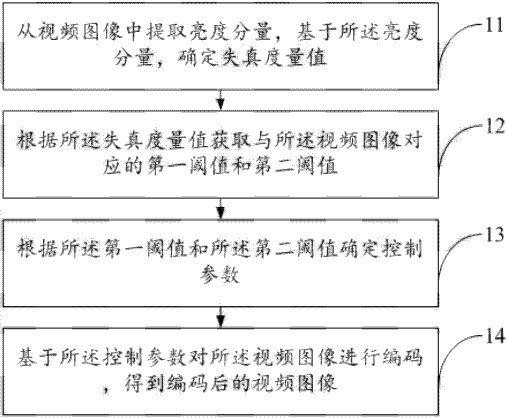
[0103] The present invention provides a coding method for video images, such as figure 1 As shown, the encoding method for video images includes:

[0104]11. Extract a luminance component from the video image, and determine a distortion metric based on the luminance component.

[0105] 12. Acquire a first threshold and a second threshold corresponding to the video image according to the distortion metric value.

[0106] 13. Determine a control parameter according to the first threshold and the second threshold.

[0107] 14. Encode the video image based on the control parameter to obtain an encoded video image.

[0108] In practice, in order to solve the defect that content adaptation cannot be performed in the existing coding technology, resulting in low coding efficiency, the present invention provides a coding method for video images, in which the distortion measurement value is obtained, based on the distortion measurement Value decomposes video frames into ordered and u...

Embodiment 2

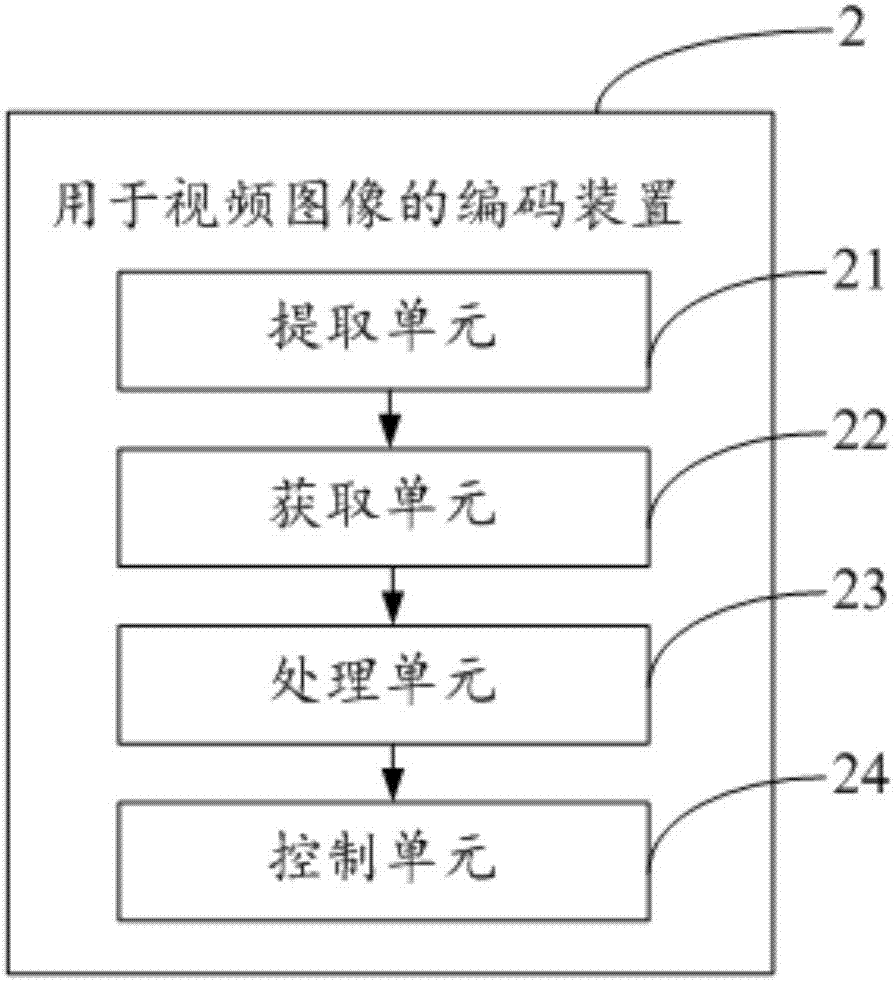
[0232] This embodiment provides a coding device 2 for video images, such as figure 2 As shown, the encoding device for video images includes:

[0233] An extraction unit 21, configured to extract a luminance component from a video image, and determine a distortion metric value based on the luminance component;

[0234] An acquisition unit 22, configured to acquire a first threshold and a second threshold corresponding to the video image according to the distortion metric value;

[0235] A processing unit 23, configured to determine a control parameter according to the first threshold and the second threshold;

[0236] The control unit 24 is configured to encode the video image based on the control parameter to obtain an encoded video image.

[0237] In practice, in order to solve the defect that content adaptation cannot be performed in the existing coding technology, resulting in low coding efficiency, the present invention provides a coding method for video images, in whi...


PUM


Abstract

The invention discloses a coding method and device for a video image, and belongs to the field of video coding and decoding. The coding method disclosed by the invention comprises the steps of: extracting a luminance component from a video image, determining a distortion measurement value, obtaining a first threshold value and a second threshold value corresponding to the video image according to the distortion measurement value, determining control parameters according to the first threshold value and the second threshold value, and coding the video image based on the control parameters, so that a coded video image is obtained. The just-noticeable difference (JND) is utilized; therefore, the weak estimation problem for the JND threshold value of a disordered region in the previous JND model is overcome; the spatial redundancy in a video sequence is effectively eliminated; the coding amount is reduced; the coding efficiency is increased; simultaneously, the JND of an ordered region is estimated more accurately by utilization of the obtained luminance mask and spatial mask, so that the perceived quality of the ordered region in a video can be well improved conveniently; and thus, the overall viewing experience of the video can be improved.

Description

technical field [0001] The invention belongs to the field of video coding and decoding processing, and in particular relates to a coding method and device for video images. Background technique [0002] High-Dynamic Range (HDR) video will be the next big thing in television. HDR video can greatly expand the contrast and color at the same time, the bright parts of the picture will be brighter, so that it looks more "depth"; and the expansion of color can make red, green, blue and all colors in between appear Brighter and purer. In order to provide high-quality visual effects while reducing the bit rate, the coding of high dynamic range (HDR) video is called the key research object in the field of current video technology. [0003] Since the final recipients of most video coded transmissions are human beings, and encoding and transmitting information that is undetectable or uninteresting to the human eye is a waste of network bandwidth, video coding algorithms should conside...

Claims


Application Information

Patent Timeline
Patent Type & Authority Applications(China)
IPC IPC(8): H04N19/154H04N19/19H04N19/186H04N19/124H04N19/117
CPCH04N19/117H04N19/124H04N19/147H04N19/154H04N19/186H04N19/19
Inventor 郑喆坤于胜韬陈瑶林桥洲李明尚国强吴钊
Owner XIDIAN UNIV
Why Eureka
Try Eureka