Dust removing method of spring tube dust remover

A dust collector and spring cartridge technology, applied in chemical instruments and methods, separation methods, membrane filters, etc., can solve problems such as slow cleaning work, decreased air permeability, cumbersome operation, etc., to improve cleaning speed, prevent excessive flying, Simple operation effect

Active Publication Date: 2017-09-29
无锡锡麦粮油装备工程有限公司
View PDF5 Cites 6 Cited by
  • Summary
  • Abstract
  • Description
  • Claims
  • Application Information

AI Technical Summary

Problems solved by technology

[0003] Cartridge dust collector is a kind of dust collector with filter cartridge as filter element and pulse injection or reverse injection. The structure is composed of air flow distribution distribution plate, filter cartridge and electric control device; the high-speed air flow carrying dust decelerates and settles after entering the dust removal chamber, and the dust adheres to the filter screen; the filter screen used for a long time is blocked by dust, and the overall air permeability decreases, so , the filter screen needs to be cleaned regularly; the traditional filter cartridge dust collector needs manual regular inspection, and the operation is more cumbersome; the dust removal method of the traditional dust collector is negative pressure back blowing dust removal, which makes the dust rise again, which is easy to cause secondary pollution; makes cleanup too slow

Method used


Image

  • Dust removing method of spring tube dust remover

Examples


Embodiment

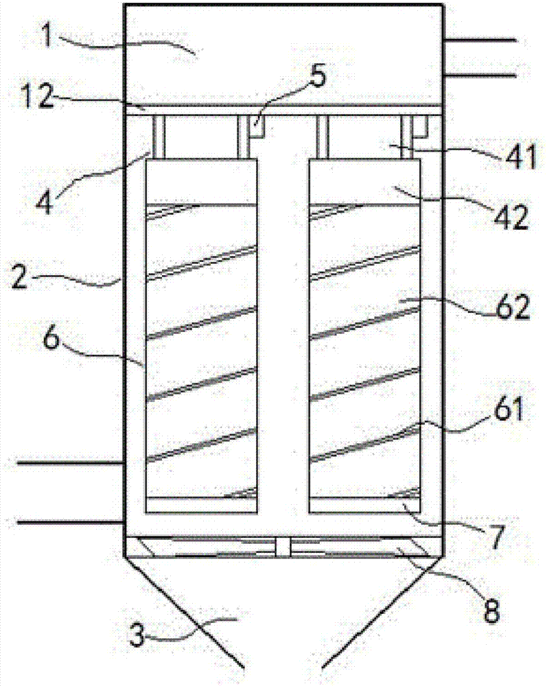
[0012] exist figure 1 In the shown embodiment, the spring cartridge dust collector includes a dust removal chamber 2, a clean chamber 1 and an ash hopper 3; Below; between the clean chamber 1 and the dedusting chamber 2 are separated by a partition 12; an air inlet pipe is installed on the side wall of the dedusting chamber 2, and an exhaust pipe is installed on the side wall of the dedusting chamber 1; The lower surface of the plate 12 is rotationally symmetrically distributed with dust removal units 4. The dust removal unit 4 includes a fixed shaft 41 and an electromagnetic ring 42. A vibrator 5 is installed on the fixed shaft 41. The electromagnetic ring 42 can move along the fixed shaft 41. The axis reciprocatingly slides; the electromagnetic ring 42 is electrically connected to the dust removal power supply; the dust removal power supply is a pulse current; the dust removal cylinder 6 is fixedly installed below the electromagnetic ring 42, and the dust removal cylinder 6 ...


PUM


Abstract

The invention relates to a dust removing method of a spring tube dust remover. The spring tube dust remover comprises a dust removing cavity, a purifying cavity and a dust hopper, wherein the purifying cavity and the dust removing cavity are separated by a separating plate; dust removing units are rotationally and symmetrically arranged on the lower surface of the separating plate; each dust removing unit comprises a fixing shaft and an electromagnetic loop; the electromagnetic loops can do reciprocating sliding along the axes of the fixing shafts; the electromagnetic loops are electrically connected with a dust removing power supply; dust removing tubes are fixedly arranged under the electromagnetic loops; the dust removing tubes and the fixing shafts are coaxially arranged; the lower ends of the dust removing tubes are fixedly arranged on conducting strips arranged at the lower part of the dust removing cavity in a sealing way; the conducting strips are electrically connected with the dust removing power supply; each dust removing tube comprises an electromagnetic spring and a dust removing net; the upper ends of the electromagnetic springs are electrically connected with the electromagnetic loops; the lower ends of the electromagnetic springs are electrically connected with the conducting strips; the electromagnetic springs are fixedly sheathed in the dust removing nets. The spring tube dust remover is novel and unique in structure and is capable of efficiently cleaning dust and effectively increasing the cleaning efficiency.

Description

[0001] This application is a divisional application whose application number is 201610002314.4 and the name of the invention is a spring dust collector. technical field [0002] The invention relates to an industrial dust collector, in particular to a filter cartridge dust collector. Background technique [0003] Cartridge dust collector is a kind of dust collector with filter cartridge as filter element and pulse injection or reverse injection. The structure is composed of air flow distribution distribution plate, filter cartridge and electric control device; the high-speed air flow carrying dust decelerates and settles after entering the dust removal chamber, and the dust adheres to the filter screen; the filter screen used for a long time is blocked by dust, and the overall air permeability decreases, so , the filter screen needs to be cleaned regularly; the traditional filter cartridge dust collector needs manual regular inspection, and the operation is more cumbersome; ...

Claims


Application Information

Patent Timeline
Patent Type & Authority Applications(China)
IPC IPC(8): B01D46/24B01D50/00B01D46/00
CPCB01D46/0036B01D46/2411B01D2275/20B01D46/76B01D50/20
Inventor 谭雪黄日娇许静璇
Owner 无锡锡麦粮油装备工程有限公司
Why Eureka
Try Eureka