Air distribution device of fluidized bed reactor

A technology of fluidized bed reactor and air distribution device, which is applied in the direction of fluidized bed combustion equipment, burning fuel in molten state, lighting and heating equipment, etc. Uneven wind and other problems, to achieve the effect of strengthening uniform air distribution, preventing hardening, and smooth slag discharge

Active Publication Date: 2017-12-08
KEDA MAS CLEAN ENERGY +2
View PDF11 Cites 0 Cited by
  • Summary
  • Abstract
  • Description
  • Claims
  • Application Information

AI Technical Summary

Problems solved by technology

[0007] Aiming at the problems of high slag residual carbon and serious waste of energy in the air distribution device of the existing fluidized bed reactor, the present invention provides an air distribution device of the fluidized bed reactor, which can provide a secondary reaction opportunity for the slag, thereby Improve the burnout rate, reduce slag residual carbon, and also make the slag waste heat be recycled, and solve the problems of difficulty in discharging large slag, low recovery rate of slag waste heat, uneven air distribution, etc.

Method used


Image

  • Air distribution device of fluidized bed reactor
  • Air distribution device of fluidized bed reactor
  • Air distribution device of fluidized bed reactor

Examples


Embodiment 1

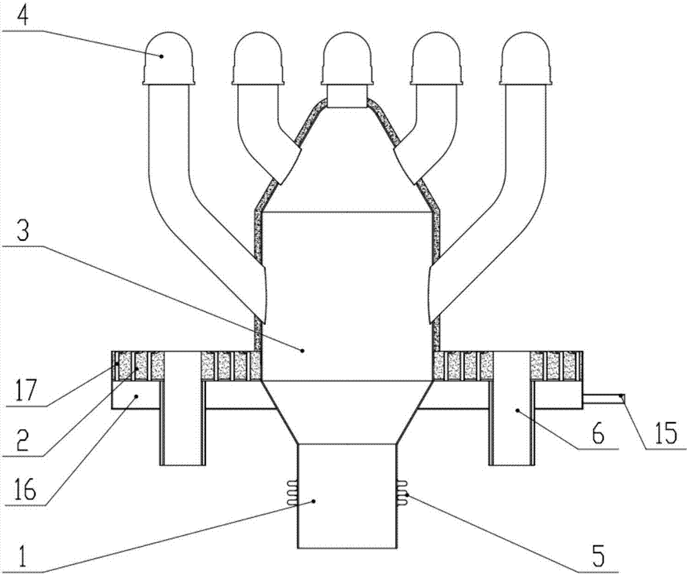
[0043] Such as figure 2 and image 3 As shown, an air distribution device for a fluidized bed reactor includes an air inlet pipe 1, a base plate 2, a gas distribution chamber 3, and a plurality of wind caps 4; the gas distribution chamber 3 is a tree structure with an inlet and a plurality of outlets, the diameters of each outlet are equal, and the axis of each outlet is parallel to the inlet; the inlet end of the gas distribution chamber 3 passes through and is fixed on the base plate 2 vertically, and it is connected to the The air inlet pipe 1 is coaxially connected, and its diameter is not smaller than the air inlet pipe 1; each outlet of the gas distribution chamber 3 is connected with one of the wind caps 4; the base plate 2 is provided with a discharge port 6.

[0044] Such as Figure 4 As shown, the coaxial connection between the inlet pipe 1 and the gas distribution chamber 3 in this embodiment avoids the bias flow of the gas, and at the same time, the gas with a ...

Embodiment 2

[0046] A kind of air distribution device of fluidized bed reactor, is basically the same as embodiment 1, difference is, as Figure 5 As shown, each outlet of the gas distribution chamber 3 has a layer of branches, which are composed of several identical branch manifolds 7; Figure 9 As shown, each of the branch manifolds 7 has a main pipe 8 and a plurality of branch pipes 9, and the outlet section of the branch pipes 9 is parallel to the axis of the main pipe 8; the diameters of each branch pipe 9 are equal, and each of the branch pipes 9 The outlet of the branch pipe 9 is flush; the wind cap 4 is arranged on the outlet of the branch pipe 9 .

[0047] In this embodiment, the gas passes through the air inlet pipe 1 through the gas distribution chamber 3 and the branch manifold 7 and finally comes out of the wind cap 4. The whole air distribution device presents a tree structure of multi-layer branch manifolds 7, which not only ensures the air distribution Uniformity, and at t...

Embodiment 3

[0049] A kind of air distribution device of fluidized bed reactor, is basically the same as embodiment 2, difference is, as Figure 6 and 7 As shown, each outlet of the gas distribution chamber 3 has a double-layer branch, and the second-layer branch replaces the air cap 4 in the second embodiment with the outlet of the branch pipe 9, and the air cap 4 is arranged at the second On the outlet of the branch pipe 9 of the branch manifold 7 in the 2-layer branch, specifically, such as Figure 8 as shown,

[0050] The outlet of the branch pipe 9 of the branch manifold 7 in the first layer of branches is coaxially connected with the inlet of the main pipe 8 of the branch manifold 7 in the second layer of branches;

[0051] The female pipe 8 described in this embodiment is a warhead structure, which is composed of a cylinder body and a head, and the head has a curved shape; the curved shape of the head is a cone or a sphere; the benefits of this feature The effect is: after the ga...


PUM


Abstract

The invention discloses an air distribution device of a fluidized bed reactor, and belongs to the field of fluidized bed equipment. The air distribution device comprises an air inlet pipe and also comprises a base plate, a gas distribution chamber and a plurality of air caps, wherein the gas distribution chamber is of a tree-like structure and has an inlet and a plurality of outlets; the outlets are the same in diameters; axes of the outlets are parallel to the inlets; an inlet end of the gas distribution chamber vertically penetrates through and is fixed on the base plate, is coaxially connected with the air inlet pipe, and has the diameter not less than that of the air inlet pipe; each outlet of the gas distribution chamber is connected with one of the air caps; a discharging port is formed in the base plate. The air distribution device provided by the invention not only can ensure smooth discharge of large slags and recovery of waste heat of furnace slag, but also can eliminate fluidization dead zones, ensure uniformity of air distribution and provide a secondary reaction opportunity for the furnace slag, so as to increase a burnout rate and reduce emission of slag and carbon residues.

Description

technical field [0001] The invention belongs to the field of fluidized bed equipment, and in particular relates to an air distribution device for a fluidized bed reactor. Background technique [0002] Such as figure 1 As shown, the existing air distribution device for a fluidized bed reactor usually adopts the structure of an air distribution plate 11; the air distribution plate 11 must not only support the weight of the entire fluidized bed reactor, but also bear the fluidized bed reaction. The high temperature in the furnace chamber 12 is as high as 1000°C; in order to ensure that the air distribution plate 11 has sufficient rigidity and strength under high temperature conditions, and will not be deformed by heat, a high-temperature heat-resistant steel plate with a large thickness is usually used as the air distribution plate 11, or On the whole, the water-cooled air distribution device is directly adopted. At the same time, the uniform air distribution in the fluidized...

Claims


Application Information

Patent Timeline
Patent Type & Authority Applications(China)
IPC IPC(8): F23C10/20
CPCF23C10/20
Inventor 王人杰任强刘欣彭敏赵航陈谦
Owner KEDA MAS CLEAN ENERGY
Why Eureka
Try Eureka