A stamping die for automatic material pushing of auto parts

A technology for stamping dies and auto parts, applied in the field of stamping dies, can solve the problems of reduced stamping accuracy, cumbersomeness, and high cost, and achieve the effects of improving stamping efficiency and processing quality, improving stamping accuracy, and improving stamping efficiency

Active Publication Date: 2019-02-01
NINGBO TUGUAN PRECISION MOLD
View PDF5 Cites 0 Cited by
  • Summary
  • Abstract
  • Description
  • Claims
  • Application Information

AI Technical Summary

Problems solved by technology

[0003] The existing stamping dies for automatic material pushing of auto parts have complex structures and relatively single performance, and have the following disadvantages:
[0004] 1. Usually direct stamping with a drill bit is easy to cause damage to auto parts during processing, and is easily affected by external vibration forces, resulting in reduced stamping accuracy;
[0005] 2. Usually manual unloading is cumbersome, time-consuming and labor-intensive, which affects the processing efficiency of auto parts. In addition, some stamping dies with automatic material pushing on the market are generally equipped with multiple jacking mechanisms, and use multiple The driving equipment driving the jacking mechanism works at the same time. This method is difficult to ensure the synchronization of multiple jacking mechanisms, and the cost is high, and there are certain limitations in use.

Method used


Image

  • A stamping die for automatic material pushing of auto parts
  • A stamping die for automatic material pushing of auto parts
  • A stamping die for automatic material pushing of auto parts

Examples


Embodiment

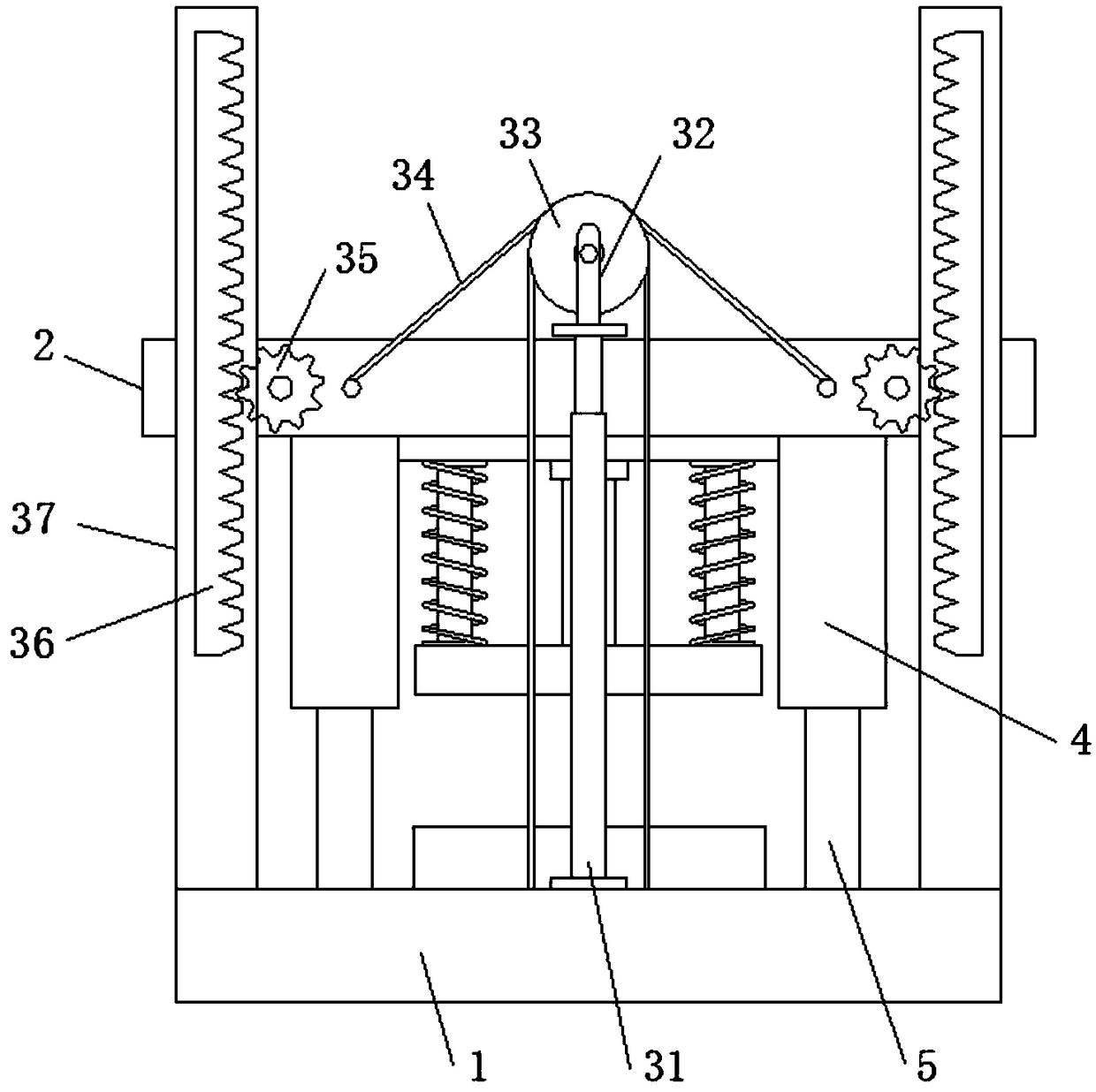
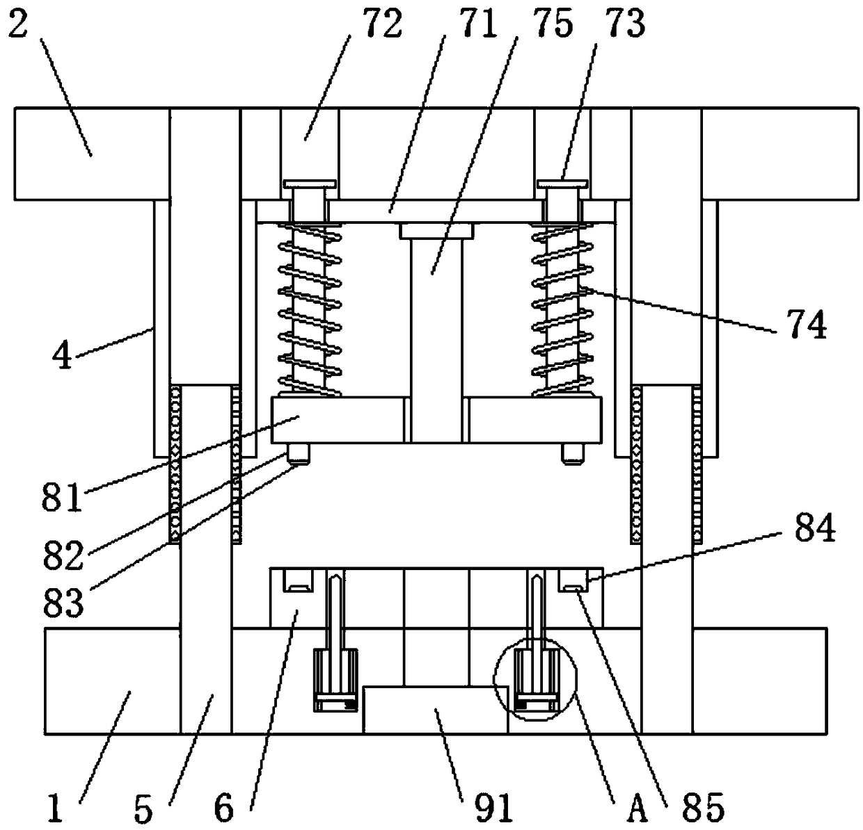
[0029] refer to Figure 1-4 , a stamping die for automatic material pushing of auto parts, comprising a bottom plate 1 and a top plate 2 arranged in parallel, the bottom plate 1 is located directly below the top plate 2, and also includes a stable lifting mechanism arranged between the bottom plate 1 and the top plate 2. The buffer mechanism at the bottom of the top plate 2 and the automatic pushing mechanism inside the bottom plate 1;

[0030] The smooth lifting mechanism includes two groups of hydraulic cylinders 31 and positioning plates 37 vertically installed on the top of the base plate 1, wherein the two groups of hydraulic cylinders 31 and positioning plates 37 are located on both sides of the top plate 2, and the top piston rod of the hydraulic cylinders 31 is equipped with U Shaped frame 32, the inner rotation of U-shaped frame 32 is equipped with pulley 33, is wound with two groups of steel ropes 34 on the pulley 33, and one end of steel rope 34 is connected to the ...


PUM


Abstract

The invention discloses a stamping die used for the automatic pushing of automobile accessories. The stamping die comprises a bottom plate and a top plate which are arranged in parallel and further comprises a stable lifting mechanism arranged between the bottom plate and the top plate, a buffering mechanism arranged at the bottom of the top plate and an automatic pushing mechanism arranged in thebottom plate, wherein the stable lifting mechanism comprises two groups of hydraulic cylinders and locating plates, which are vertically mounted at the top of the bottom plate, and the two groups ofhydraulic cylinders and locating plates are located at the two sides of the top plate; a U-shaped carrier is mounted on piston rods at the tops of the hydraulic cylinders, and a pulley is mounted in the U-shaped carrier in a rotating manner; two groups of steel ropes are wound on the pulley, one ends of the steel ropes are correspondingly connected to the two sides of the top of the bottom plate,and the other ends of the steel ropes are correspondingly connected to the two sides of the top plate; and gears are further mounted at both sides of the top plate in a rotating manner, and the sides,close to the top plate, of the locating plates are both provided with racks. The stamping die is reasonable in design and high in stamping precision, protects the automobile accessories from damage,achieves the automatic pushing purpose, increases the stamping efficiency of the automobile accessories, and improves the machining quality.

Description

technical field [0001] The invention relates to the technical field of stamping dies, in particular to a stamping die for automatic material pushing of auto parts. Background technique [0002] Today's high-strength steel and ultra-high-strength steel have realized the lightweight of vehicles and improved the collision strength and safety performance of vehicles, so they have become an important development direction of automotive steel. However, with the improvement of the strength of the sheet metal, the traditional cold stamping process is prone to cracking during the forming process, which cannot meet the processing requirements of high-strength steel plates. In the case that the forming conditions cannot be met, the hot stamping forming technology of ultra-high-strength steel plates is gradually being studied internationally. This technology is a new process that integrates forming, heat transfer and structural phase transformation. It mainly uses the characteristics o...

Claims


Application Information

Patent Timeline
Patent Type & Authority Patents(China)
IPC IPC(8): B21D37/10B21D45/04
Inventor 翁江辉
Owner NINGBO TUGUAN PRECISION MOLD
Why Eureka
Try Eureka