Hydraulic system for loading test

A hydraulic system and loading test technology, which is applied to fluid pressure actuation system components, fluid pressure actuation devices, servo motor components, etc., can solve the problems of unstable test performance, difficult torque control, and complex control system, etc., to achieve Easy to change load, good control of loading torque, and stable test performance

Inactive Publication Date: 2018-01-19
柳州北斗星液压科技有限公司
View PDF0 Cites 2 Cited by
  • Summary
  • Abstract
  • Description
  • Claims
  • Application Information

AI Technical Summary

Problems solved by technology

The mechanically enclosed test bench has complex mechanical structure, low transmission efficiency, difficult to change the load during operation, difficult to control the torque, unstable test performance, and poor versatility
The electric closed loading method also has the disadvantages of complex control system and high investment

Method used


Image

  • Hydraulic system for loading test

Examples


Embodiment

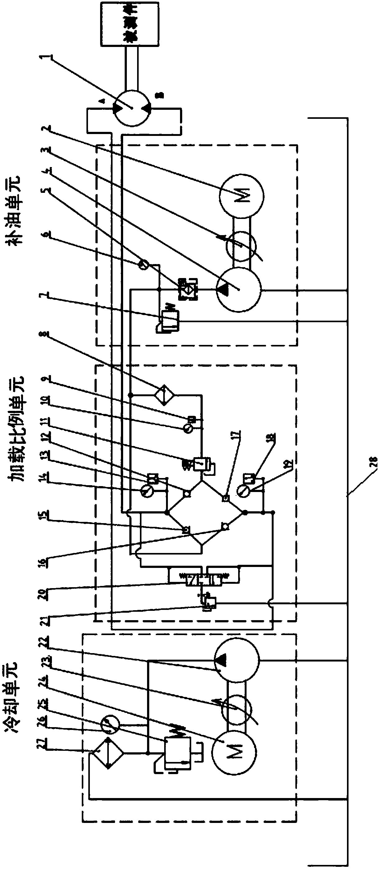
[0030] Such as figure 1 Shown is the schematic composition diagram of the hydraulic system of the present invention. The hydraulic system includes a motor 1, an oil supply unit, a load proportional unit, a low-pressure cooling unit and an oil tank.

[0031] Motor 1 is a variable displacement motor, used as a bi-directional pump, with two oil inlet and outlet ports (A oil inlet and outlet and B oil inlet and outlet), both of which are high-pressure oil ports, which can rotate in both directions and load in both directions. A fourth pressure gauge 19 and a third pressure sensor 18 are arranged on the A oil inlet and outlet pipeline, and a third pressure gauge 14 and a second pressure sensor 13 are arranged on the B oil inlet and outlet pipeline. During operation, the component under test (such as the output shaft of the gearbox) is connected with the shaft of the motor 1 .

[0032] The oil replenishment unit includes a first motor 2 , a first connecting piece 3 , a first oil p...


PUM


Abstract

The invention discloses a hydraulic system for a loading test. The hydraulic system for the loading test comprises a motor, an oil feeding unit, a load ratio unit, a low-pressure cooling unit and an oil tank. The hydraulic system is easy to change the load, easy to control, stable in test performance, excellent in generality and low in investment cost.

Description

technical field [0001] The invention relates to the technical field of detection of components such as gearboxes, reduction boxes, motors, and motors, and in particular to a hydraulic system for loading tests on components such as gearboxes, reduction boxes, hydraulic motors, and motors. The torque is subjected to a continuous two-way loading test. Background technique [0002] At present, there are two main types of loading tests: one is open type, the other is closed type, and closed type is divided into mechanically closed type and electric closed type. The mechanically closed test bench has complex mechanical structure, low transmission efficiency, difficult to change the load during operation, difficult to control the torque, unstable test performance and poor versatility. The electric closed loading method also has the disadvantages of complex control system and high investment. Contents of the invention [0003] The object of the present invention is to provide a ...

Claims


Application Information

Patent Timeline
Patent Type & Authority Applications(China)
IPC IPC(8): F15B13/02F15B21/04
Inventor 武永星孙海艳
Owner 柳州北斗星液压科技有限公司
Why Eureka
Try Eureka