Vibration shaking bed

A technology for driving rods and boxes, applied in the directions of shaking/oscillating/vibrating mixers, dissolving, mixers, etc. Good mixing effect

Inactive Publication Date: 2018-02-02
WUHAN BAIQI TECH CO LTD
View PDF0 Cites 2 Cited by
  • Summary
  • Abstract
  • Description
  • Claims
  • Application Information

AI Technical Summary

Problems solved by technology

However, the existing shakers generally only move in a single horizontal direction or in a

Method used


Image

  • Vibration shaking bed
  • Vibration shaking bed
  • Vibration shaking bed

Examples


Embodiment Construction

[0020] The principles and features of the present invention are described below in conjunction with the accompanying drawings, and the examples given are only used to explain the present invention, and are not intended to limit the scope of the present invention.

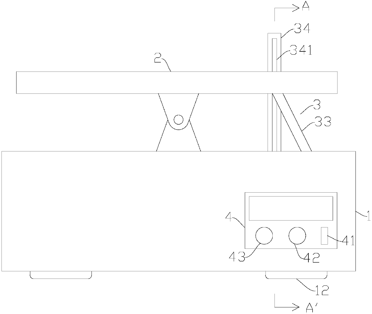
[0021] Such as figure 1 As shown, a vibrating shaker includes a box body 1, a tray 2 and a rocking mechanism 3, the tray 2 is arranged above the box body 1, and the middle part of the tray 2 is hinged to the box body 1.

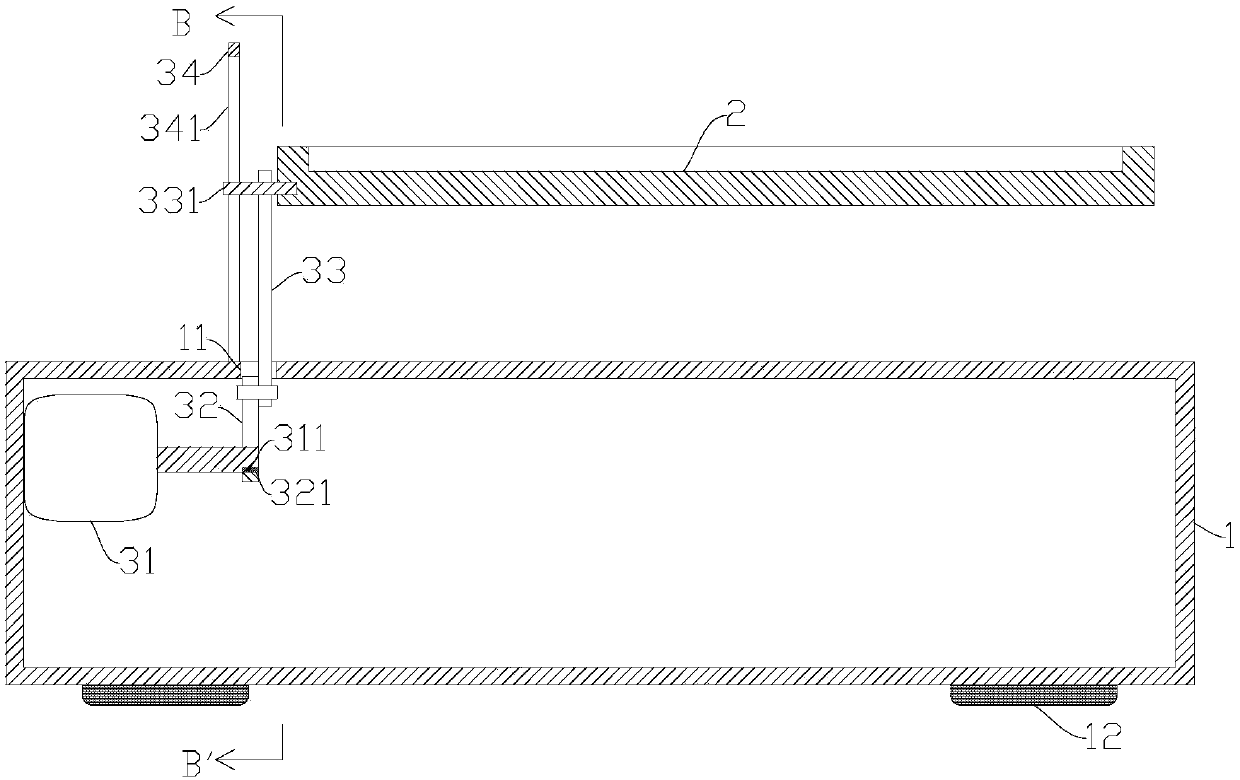
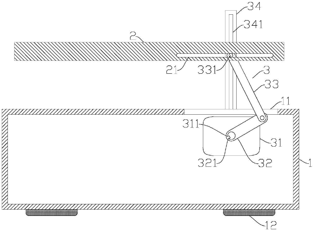
[0022] Such as figure 2 and image 3 As shown, the swing mechanism 3 includes a motor 31, a connecting rod 32 and a drive rod 33, the motor 31 is fixed in the box body 1; On the output shaft of the motor 31, and can be rotated under the drive of the output shaft of the motor 31, the output shaft of the motor 31 is provided with a slot 311, and the connecting rod 32 is provided with a protrusion 321 matching the slot 311. One end of the rod 32 is locked in the slot 311 through the protrusion 321...


PUM


Abstract

The invention relates to a vibration shaking bed. The vibration shaking bed comprises a box body, a tray and a shaking mechanism, wherein the tray is arranged above the box body; a middle part of thetray is hinged to the box body; the shaking mechanism comprises a motor, a connecting rod and a driving rod; the motor is fixed in the box body; the connecting rod is mutually perpendicular to an output shaft of the motor; one end of the connecting rod is arranged on the output shaft of the motor in a sleeving manner while the other end of the connecting rod is hinged to one end of the driving rod; a guiding column is arranged at the other end of the driving rod; a first guiding groove matched with the guiding column is arranged on the tray; the shaking mechanism also comprises a guiding rod fixed on the box body; the guiding rod is arranged on one side, away from the tray, of the driving rod; a second guiding groove matched with the guiding column is formed in the guiding rod; the guidingcolumn is also arranged in the second guiding groove in an embedding manner. The tray of the vibration shaking bed disclosed by the invention is shaken leftwards and rightwards, so that materials canbe shaken uniformly; compared with an existing tray which does single horizontal direction movement and circular motion, the tray of the vibration shaking bed disclosed by the invention has the advantages of larger vibration amplitude and better uniform mixing effect; moreover, time is saved.

Description

technical field [0001] The invention relates to the technical fields of biology and medical equipment, in particular to a vibrating shaker. Background technique [0002] With the development of scientific research, shakers, as common laboratory equipment, are widely used in biology, medicine, food, chemical industry and other fields. The shaking table realizes the mixing of liquid or cells placed on the tray, test tubes, packaging bags and other containers through the movement of the tray. However, the existing shaking table generally only moves in a single horizontal direction or in a circular motion, the vibration amplitude is small, and the time required for mixing is relatively long. Contents of the invention [0003] The technical problem to be solved by the present invention is to provide a vibrating shaker to overcome the above-mentioned deficiencies in the prior art. [0004] The technical scheme of the present invention to solve the above-mentioned technical pro...

Claims


Application Information

Patent Timeline
IPC IPC(8): B01F11/00B01F15/00
CPCB01F31/26B01F35/22142B01F35/22161B01F35/3204
Inventor 不公告发明人
Owner WUHAN BAIQI TECH CO LTD
Why Eureka
Try Eureka