Folding inflatable raft

An inflatable raft and foldable technology, which is applied in the field of hydraulic mechanical devices, can solve the problems of increased resistance in water, slow down of driving speed, and influence on the overall performance of the vehicle, and achieve the effects of sensitive action response, reliable performance, and convenient loading and unloading

CN107650599AInactive Publication Date: 2018-02-02赵兴华
5 Cites 0 Cited by

Patent Information

Authority / Receiving Office
CN · China
Current Assignee / Owner
Publication Date
2018-02-02
Estimated Expiration
Not applicable · inactive patent

Smart Images

  • Figure 1
    Figure 1
  • Figure 2
    Figure 2
  • Figure 3
    Figure 3
Patent Text Reader

Abstract

The invention discloses a folding inflatable raft. The folding inflatable raft comprises an inflatable raft body, a keel, supports, a boom cylinder, a mounting base, a lifting cylinder, a lifting cylinder base, a control cylinder, a control cylinder base, a hinge pin, fastening bolts and connecting plates, wherein the surface of the inflatable raft body is provided with a plurality of reinforcingcloth rings and insertion openings; the supports are fixedly installed on the two sides of the keel in order through the fastening bolts; the boom cylinder is installed on the keel in a sleeving modein order through a spline shaft and the fastening bolts, the lifting cylinder base is sleeved with the lifting cylinder, and the control cylinder base is sleeved with the control cylinder; and the mounting base is fixedly installed on the side face of a vehicle body in order, the lifting cylinder base is fixedly installed on the connecting plates 12 in order, and the control cylinder base is fixedly installed at the bottom of the vehicle body in order. The folding inflatable raft is scientific in design, compact in structure, reliable in performance, convenient to assemble and disassemble andlow in cost, and can be matched with various wheel-type or crawler-type amphibious vehicles and ordinary engineering vehicles, thereby better meeting the urgent demand of home and abroad for manufacturing and refitting the various amphibious vehicles.
Need to check novelty before this filing date? Find Prior Art

Description

technical field

[0001] The invention relates to a general hydraulic mechanical device, in particular to a foldable inflatable raft which can be installed on both sides of a vehicle. Background technique

[0002] At present, for the multi-wheeled or crawler-type amphibians manufactured at home and abroad, the wheels or crawlers and the car body are immersed in the water when wading and floating, resulting in a sharp increase in water resistance and a significant slowdown in travel speed, which greatly affects overall performance of the vehicle. Contents of the invention

[0003] The purpose of the present invention is to provide a "foldable inflatable raft" with scientific design, compact structure, reliable performance, convenient loading and unloading, low cost, and can be matched with various wheeled or tracked amphibious vehicles and ordinary engineering vehicles. ". The foldable inflatable raft installed on both sides of the vehicle is controlled in an orderly manner...

Examples

Embodiment Construction

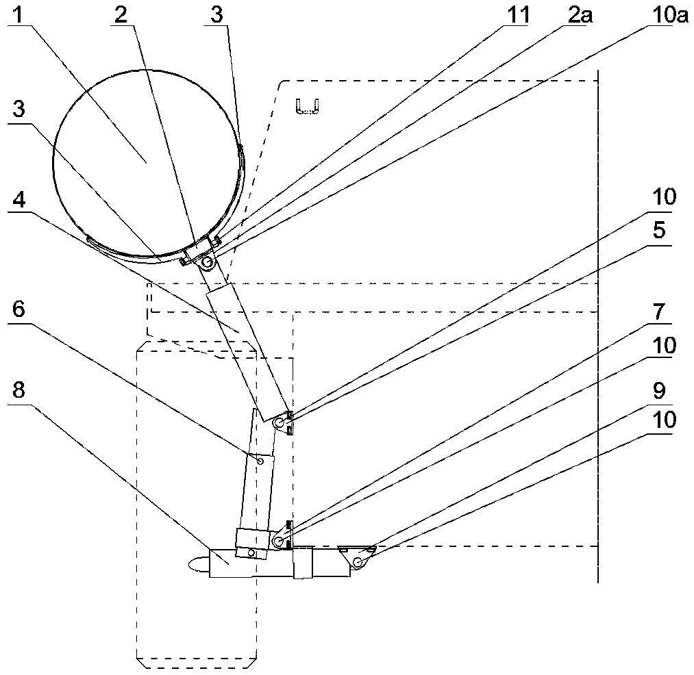
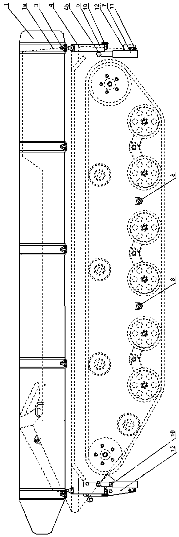
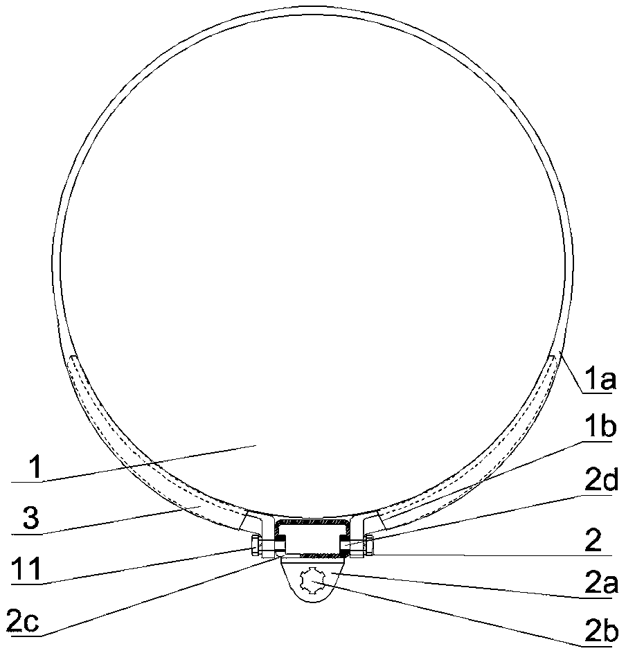
[0024] Depend on figure 1 , figure 2 and image 3 It can be seen that the present invention includes an inflatable raft 1, a keel 2, a bracket 3, a boom cylinder 4, a mounting seat 5, a lifting cylinder 6, a lifting cylinder seat 7, a control cylinder 8, a control cylinder seat 9, a pin shaft 10, and a fastening bolt 11 and connecting plate 12.

[0025] Depend on figure 1 , figure 2 , image 3 , Figure 4 , Figure 5 and Figure 6 It can be seen that the surface of the inflatable raft 1 is provided with a number of reinforced cloth rings 1a, and the sockets 1b are arranged in an orderly manner on the reinforced cloth rings 1a, and the connecting seat 2a is arranged in an orderly manner on the keel 2, and the spline hole 2b is arranged on the connecting seat 2a. Insertion holes 2c are arranged in an orderly manner on the sides, and screw holes 2d are arranged in an orderly manner on both sides. The head end of the bracket 3 is inserted into the socket 1c on the inflat...