Device detection method

A detection method and device technology, applied in instruments, measuring devices, scientific instruments, etc., can solve problems such as poor quality of assembled products, and achieve the effects of controlling costs, ensuring accuracy, and reducing complexity

Active Publication Date: 2018-03-13
NINGBO SUNNY OPOTECH CO LTD
View PDF7 Cites 25 Cited by
  • Summary
  • Abstract
  • Description
  • Claims
  • Application Information

AI Technical Summary

Problems solved by technology

[0006] Aiming at the problems in the related technologies, the present invention proposes a device detection method, which can effectively inspect the devices and solve the problem of poor quality of assembled products

Method used


Image

  • Device detection method
  • Device detection method
  • Device detection method

Examples


example

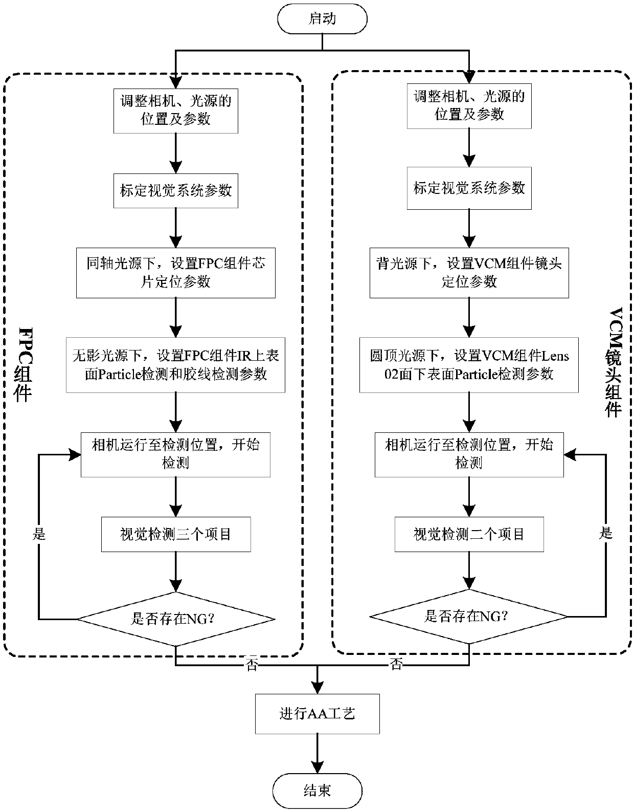
[0072] The following will take the AA device as an example to describe the detection method according to the present invention. In this example, the detection method according to the embodiment of the present invention is executed in parallel to locate and detect the FPC component and the VCM component respectively.

[0073] like figure 1 As shown, the process of detecting FPC components and VCM components according to the pre-detection method of the present invention is as follows.

[0074] For FPC components, the following inspection steps can be performed:

[0075] (1) During the detection of FPC components, the position and parameters of the camera and light source (including aperture, exposure time, light source brightness, etc.) can be adjusted first, specifically including: adjusting the vertical position of the camera so that the chip of the FPC component is in the focus position, And adjust the exposure time and gain of the camera to make the chip image of the FPC c...


PUM


Abstract

The invention discloses a device detection method, which comprises the following steps: irradiating the surface of a device for a test by a first light source, taking a photo of the device under the irradiation of the first light source to obtain a first image; according to the first image, positioning the device; irradiating the surface of the device by a second light source, taking a photo of the device under the irradiation of the second light source to obtain a second image; and analyzing the second image to determine whether the device is qualified or not. The provided method can carry out positioned detection and defect detection on a device, the position where the device stays can be accurately positioned, at the same time, the device can be detected to determine whether the deviceis qualified or not, the subsequent operation such as calibration, assembling, and the like, becomes convenient, and the product quality is improved effectively. Moreover, the integrated operation ofpositioning and defect detection is realized, the device does not need to be transmitted between different stations, and the detection efficiency is improved.

Description

technical field [0001] The present invention relates to the field of device detection, and in particular, to a device detection method. Background technique [0002] In the development of active alignment (Active Alignment, referred to as AA) equipment, it is necessary to glue the flexible circuit board (abbreviated as FPC) assembly, and to connect the FPC assembly with the lens assembly (the lens assembly includes a lens and a motor, the The motor can be a Voice Coil Motor (VCM), so the lens assembly can be called a VCM assembly) and the AA action can only be performed after it is positioned at the pre-clearing position. [0003] During the alignment process, the position of the FPC component and the VCM component in the jig will deviate. If the positioning compensation is not performed, the AA operation will not be able to accurately align the FPC and the VCM. In the utility model patent with the authorized notification number CN 205067834 U, a lens adsorption jig for act...

Claims


Application Information

Patent Timeline
Patent Type & Authority Applications(China)
IPC IPC(8): G01N21/95G01N21/956
CPCG01N21/95G01N21/956G01N2021/9511G01N2021/95638
Inventor 诸庆张鼎谷新
Owner NINGBO SUNNY OPOTECH CO LTD
Why Eureka
Try Eureka