Photoelectric angle measuring device

An angle measurement device, photoelectric technology, applied in the field of measuring instruments, can solve the problems of the minimum unit limit of the dial scale, low measurement accuracy, data error, etc., and achieve the effect of improving accuracy

Inactive Publication Date: 2018-03-23
四川零点自动化系统有限公司
View PDF1 Cites 4 Cited by
  • Summary
  • Abstract
  • Description
  • Claims
  • Application Information

AI Technical Summary

Problems solved by technology

[0004] However, the minimum unit of the dial scale of this angle measuring instrument is limited to a certain extent, and there is a certain error in reading the data by humans, so the measurement accuracy is low, and it is not suitable for some instruments that require high measurement accuracy of inclination angles.

Method used


Image

  • Photoelectric angle measuring device
  • Photoelectric angle measuring device
  • Photoelectric angle measuring device

Examples


Embodiment 1

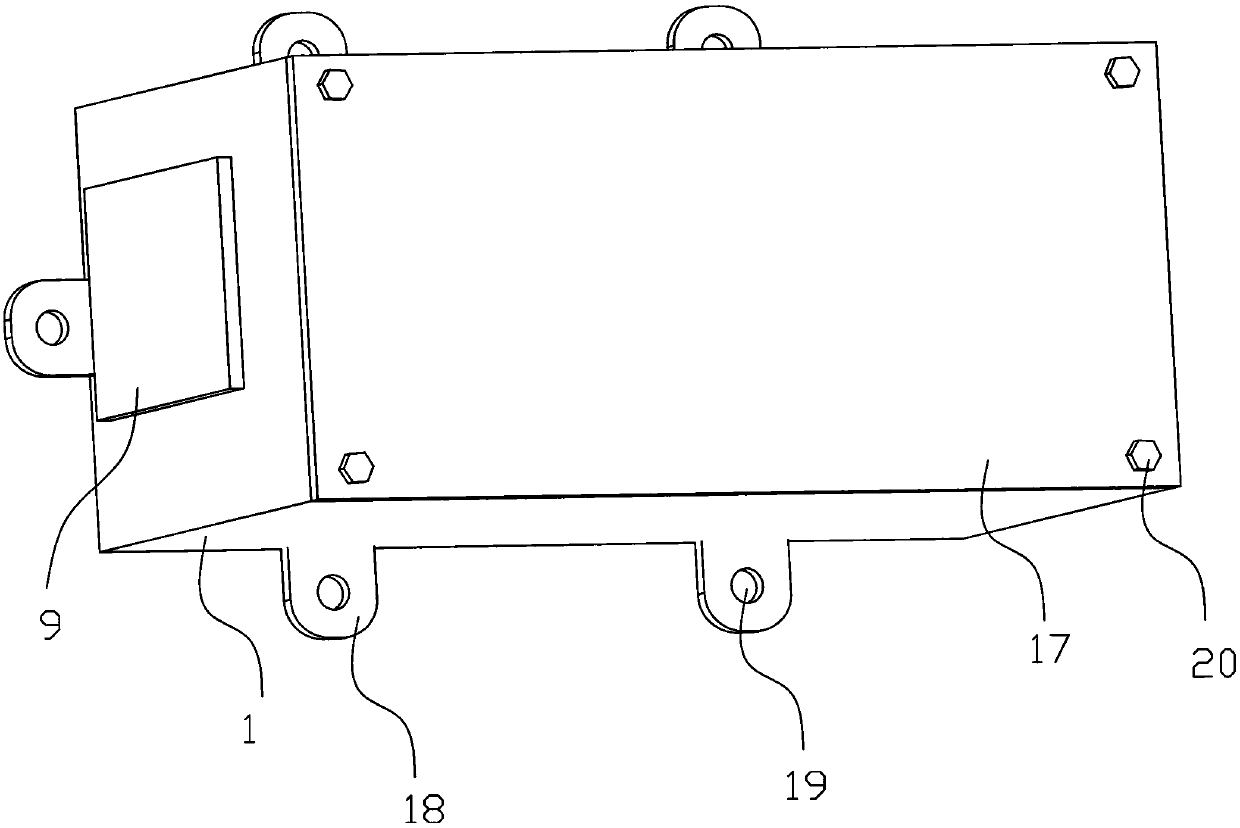
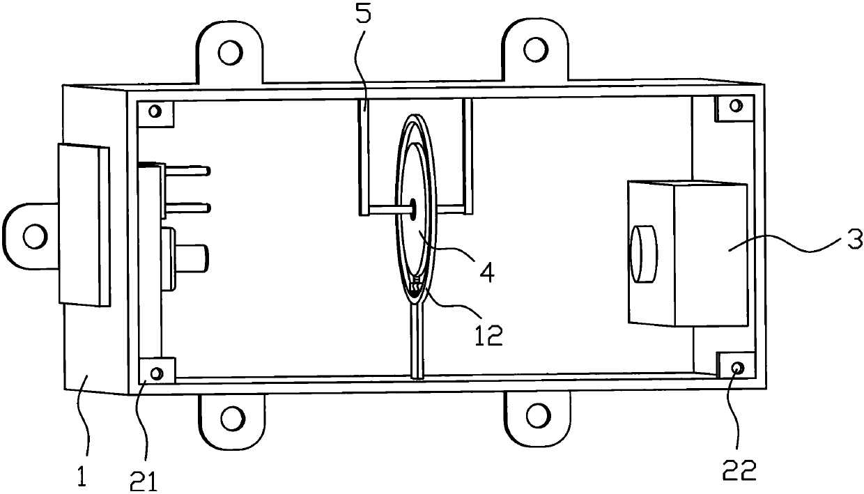
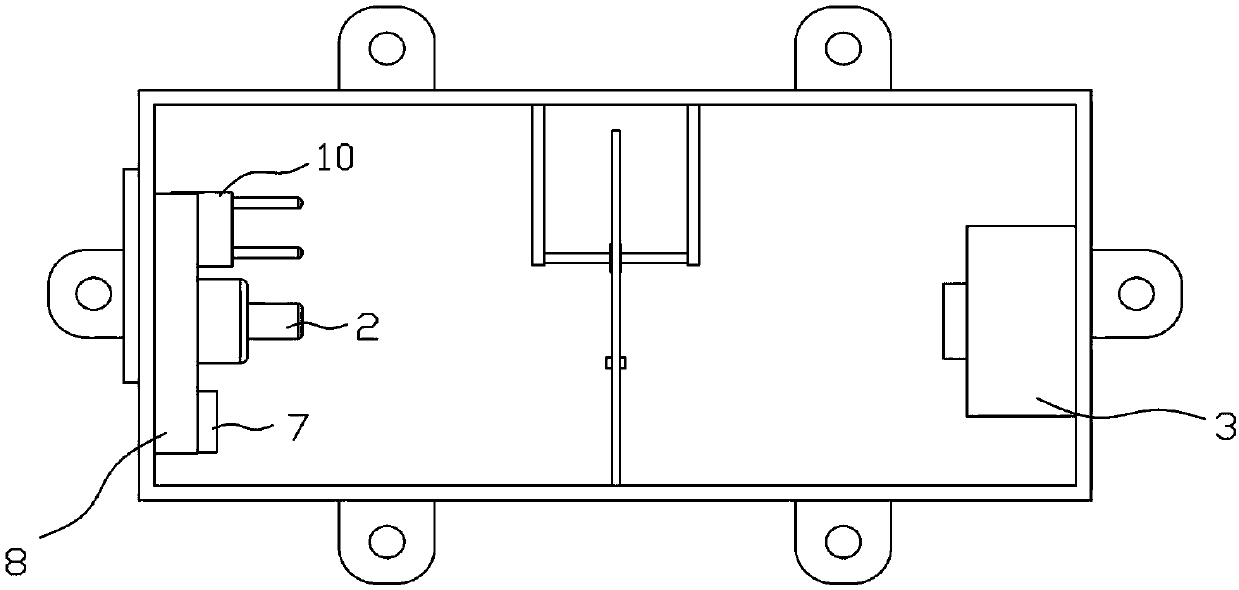
[0038] like Figures 1 to 7 As shown, this embodiment provides a photoelectric angle measuring device, which includes a closed cuboid-shaped accommodating chamber 1, and the accommodating chamber 1 is made of an opaque material, which can prevent external light from entering the accommodating chamber 1 inside. One end of the accommodating chamber 1 is provided with a laser transmitter 2 , the other end of the accommodating chamber 1 is provided with an illuminance meter 3 , and a cylindrical filter 4 is arranged between the laser transmitter 2 and the illuminance meter 3 . The light sheet 4 can rotate around its own axis, and the laser light emitted by the laser transmitter 2 passes through the light filter 4 and finally irradiates the receiving head of the illuminometer 3 . The laser path is perpendicular to the surface of the filter 4. The filter 4 is made of uniform glass. The light transmittance of the filter 4 gradually decreases from a certain radius of the cross-sectio...

Embodiment 2

[0041] like Figures 1 to 7 As shown, this embodiment is further improved on the basis of Embodiment 1, specifically, a communication module 10 is further provided in the accommodation chamber 1 for sending the angle signal obtained by the microprocessor 7 to the terminal receiving device.

Embodiment 3

[0043] like Figures 1 to 7As shown, this embodiment is further improved on the basis of Embodiment 1 and Embodiment 2. Specifically, a rolling bearing 11 is provided at the axial center of the optical filter 4, and the rolling bearing 11 is fixed in the accommodating chamber 1 through the bracket 5. on the side wall. A resistance ring 12 is coaxially arranged around the edge of the optical filter 4 , and the resistance ring 12 is made of rubber.

[0044] In order to easily adjust the distance between the counterweight 6 and the resistance ring 12, the counterweight 6 is arranged in a cylindrical shape, the axis of the counterweight 6 coincides with the axis of the threaded rod 14, and the side of the counterweight 6 is provided with anti-skid patterns 15.

[0045] One side of the accommodating chamber 1 is provided with an opening 16 and a sealing cover 17, the sealing cover 17 can be fixed at the opening 16 of the accommodating chamber 1 by four fastening bolts 20, and the ...


PUM


Abstract

The invention discloses a photoelectric angle measuring device, which relates to the technical field of measuring instruments and solves the problem of low measurement accuracy of an object's inclination angle in the prior art. A laser emitter is provided, and an illuminance meter located on the laser path emitted by the laser emitter is provided. A filter that can rotate around its own axis is arranged on the laser path between the laser emitter and the illuminance meter. The laser path and the filter The surface is vertical, and the light transmittance of each part of the filter is different. The filter is fixed in the accommodation chamber through the bracket, and the edge of the filter is provided with a counterweight. The accommodation chamber is also equipped with a microprocessor and a power module. A display screen is arranged outside the chamber, and the illuminance meter, the power supply module, and the display screen are respectively electrically connected to the microprocessor. The invention uses electronic technology to calculate the inclination angle of the object, and has the advantage of high measurement accuracy.

Description

technical field [0001] The invention relates to the technical field of measuring instruments, and more particularly to a photoelectric angle measuring device. Background technique [0002] In some fields such as scientific research, it is often necessary to accurately measure the tilt angle of some instruments. For example, the astronomical telescope in some observatories needs to precisely control the tilt angle of the telescope to receive the signals emitted by different stars. For the stars observed by scientists , if the tilt angle of the astronomical telescope is slightly deviated, the received signal may change greatly. [0003] Chinese Patent Publication No. CN206378069U discloses an angle measuring instrument, which includes a scale dial and a dial scale. The center of the scale dial is provided with a central axis, a pointer is provided on the central axis, and a weight is provided at the end of the pointer. When in use, fix the scale dial on the object to be measu...

Claims


Application Information

Patent Timeline
Patent Type & Authority Applications(China)
IPC IPC(8): G01B11/26
CPCG01B11/26
Inventor 王永贵廖亮郭静
Owner 四川零点自动化系统有限公司
Why Eureka
Try Eureka