
Mounting side waterproof structure of photovoltaic battery piece

A photovoltaic cell and waterproof structure technology, which is applied to the support structure of photovoltaic modules, photovoltaic power generation, photovoltaic modules, etc., can solve the problems such as the frame cannot be waterproof and the appearance is not beautiful, and achieve the effect of not affecting the appearance and wide application prospects.

Inactive Publication Date: 2018-04-20
河南英电环保股份有限公司
View PDF0 Cites 0 Cited by
  • Summary
  • Abstract
  • Description
  • Claims
  • Application Information

AI Technical Summary

Problems solved by technology

However, when this structural device is laid on the roof, the frame between two adjacent battery sheets cannot be waterproof, so that water seeps into the house, and the appearance is not beautiful.

Method used


Image

  • Mounting side waterproof structure of photovoltaic battery piece
  • Mounting side waterproof structure of photovoltaic battery piece

Examples


Embodiment 1

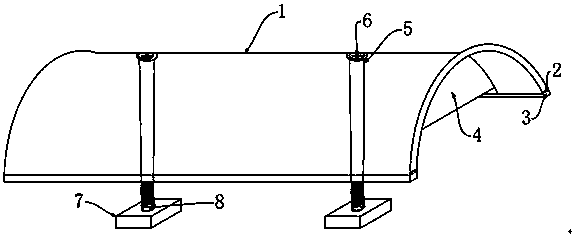
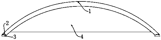
[0015] Such as figure 1 , figure 2 The waterproof structure on the installation side of the photovoltaic cells, the plate body 1 is a concave arc structure, the distance between the arc-shaped top of the plate body 1 and the plane where the bottom end is located is 10-30 mm, and the distance between the two sides of the plate body 1 is The distance between the plate body 1 and the width is 80~120mm. The specific width can be determined according to the frame width of different cells. The concave arc structure of the plate body 1 can maximize the drainage, so that the rainwater falling on the plate body 1 can flow down as soon as possible. , conducive to drainage. T-shaped grooves 2 are provided on both sides of the board body 1, and rubber pads 3 are arranged in the T-shaped grooves 2. The rubber pads 3 extend outside the board body 1 and are located directly below the side end faces. The horizontal plane is parallel, the thickness of the rubber pad 3 is 5~8mm, the width of...

Embodiment 2

[0017] When using the waterproof structure on the installation side of the photovoltaic cells of the present invention, first lay the photovoltaic cells on the roof, and place the fixing block 7 of the waterproof device under the cells while laying the adjacent cells, and then put the screws 6 through the Through the first through hole 5 and screwed into the second through hole 8 of the fixing block 7, this step is only to connect the board body 1 and the fixing block 7, and then install the adjacent photovoltaic cells, after the adjacent cells are installed , and finally adjust the position and direction of the plate body 1, and then further tighten the screw 6 until the rubber pad 3 is tightly connected with the glass of the cell, and the installation of the waterproof device is completed.

[0018] The technical solution of the present invention can solve the problem of water leakage between two adjacent cells when the photovoltaic cell is installed on the roof, and at the sa...


PUM


Abstract

The invention relates to the technical field of solar photovoltaic power generation application, particularly a mounting side waterproof structure of a photovoltaic battery piece. The mounting side waterproof structure comprises a plate body, wherein the plate body adopts an arc-shaped structure; T-shaped grooves are formed in the two side end planes of the plate body; rubber cushions are arrangedin the grooves; the rubber cushions extend to the outside of the plate body to be positioned below the side end planes; the two side end planes of the plate body are parallel to the horizontal plane;baffles are arranged at the two ends of the plate body; the lower end planes of the baffles are smaller than that of the plate body; first through holes are formed in the arc-shaped top of the platebody; fixed blocks are arranged outside the plate body; and the plate body and the fixed blocks are connected through the first through holes via screws. By virtue of the mounting side waterproof structure, the problems of non-waterproof property and non-attractive appearance after the photovoltaic battery piece is mounted on the roof can be solved; and the mounting side waterproof structure has wide application prospect in the technical field of the solar photovoltaic power generation application.

Description

technical field [0001] The invention relates to the technical field of solar photovoltaic power generation applications, in particular to a waterproof structure on the installation side of photovoltaic cells. Background technique [0002] Solar energy is one of the energy sources developed at home and abroad. It uses photovoltaic cells to absorb the sun's light energy and convert it into electrical energy. It has great potential and prospects to replace traditional energy sources. At present, solar modules mainly use tempered glass and backplane to encapsulate the cells, and then use aluminum profiles for reinforcement and as installation brackets. However, when this structural device is laid on the roof, the frame between two adjacent battery sheets cannot be waterproof, so that water seeps into the house, and the appearance is not beautiful. Contents of the invention [0003] In order to solve the above problems, a waterproof structure on the installation side of the ph...

Claims


Application Information

Patent Timeline
Patent Type & Authority Applications(China)
IPC IPC(8): H02S20/23H02S40/10H02S40/00
CPCH02S20/23H02S40/00H02S40/10Y02B10/10Y02E10/50
Inventor 侯川刘伟龙薛红波陈仲立武文臣赵康乐李铮
Owner 河南英电环保股份有限公司
Learn More