Connection structure and connection method for non-pressure tubes between modularized upper floor and lower floor

A technology for connecting structures and pressure pipes, applied in the direction of pipes/pipe joints/fittings, pipes, branch pipelines, etc., can solve the problems of increased engineering volume and maintenance costs, non-compliance with specifications, high civil construction costs, and achieve positioning effect. Good, good fire resistance effect, simple construction process

Active Publication Date: 2017-12-01
优积建筑科技发展(上海)有限公司
View PDF5 Cites 3 Cited by
  • Summary
  • Abstract
  • Description
  • Claims
  • Application Information

AI Technical Summary

Problems solved by technology

[0004] 1. Since the free stroke of the expansion joint is only 50mm, once the sewage pipe is blocked, it is difficult to replace the pipe after it is disconnected, so that the lap length of the two ends is only about 20mm, which does not meet the requirements of the specification (the specification requires a lot of lap length at 45mm)
[0005] 2. The floor of the bathroom needs to be subsidence, water stop ring, waterproof membrane, closed water test, and water removal treatment, that is, caissons need to be set up, and the existing caisson construction process needs to be set up with several support partitions, and the caisson is divided into several small parts by the support partitions. After the sewage pipes and floor drain pipes are connected, they need to be backfilled, and leveling layers, drainage slopes, waterproof layers, etc. need to be done. The cost of civil construction is high and difficult.
Since the water accumulated in the backfill layer cannot be drained naturally, the floor needs to be removed to dig up the backfill layer to pump water, which is equivalent to redecorating the bathroom, which increases the amount of work and maintenance costs
[0006] 3. Holes need to be reserved when pouring concrete on the upper and lower floors. After the pipeline construction is completed, it is necessary to carry out a series of follow-up constructions such as formwork lifting, product protection, grouting sealing, formwork removal, closed water leakage inspection, etc. The construction process is complicated

Method used


Image

  • Connection structure and connection method for non-pressure tubes between modularized upper floor and lower floor
  • Connection structure and connection method for non-pressure tubes between modularized upper floor and lower floor
  • Connection structure and connection method for non-pressure tubes between modularized upper floor and lower floor

Examples


Embodiment Construction

[0049] The connection structure and method between the pressure-free pipes on the upper and lower floors of the modules of the present invention will be further described in detail below in conjunction with specific drawings.

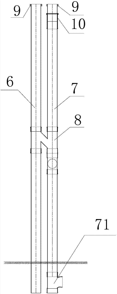
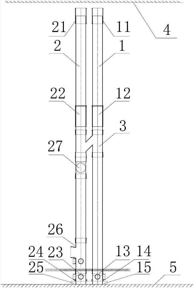
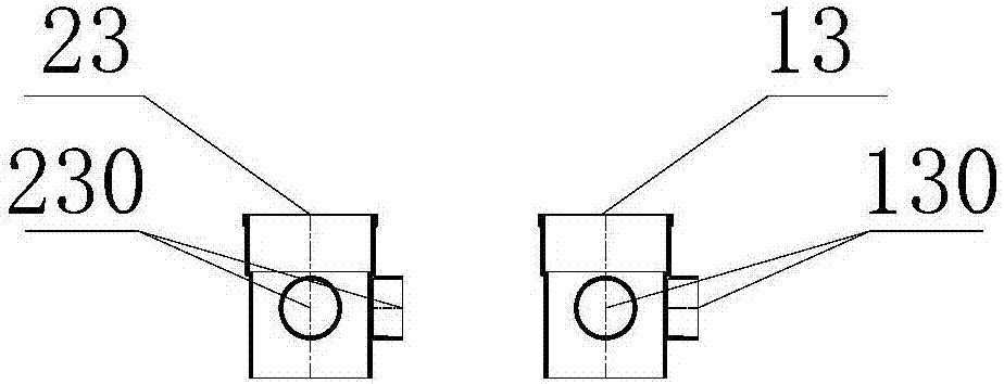
[0050] Such as figure 2As shown, it is a connection structure between the pressure-free pipes on the upper and lower floors of the modules of the present invention, including the ventilation riser 1 and the drainage riser 2 arranged between the upper module 4 and the lower module 5, the ventilation riser 1 An H pipe 3 is connected between the drainage riser 2, the drainage riser 2 is provided with a vertical inspection port 27, the top of the ventilation riser 1 is provided with a first direct pipe fitting 11, and the middle and upper part is provided with a first telescopic Section 12, the lower part is provided with the first four-way embedded part 13, the first four-way embedded part 13 is covered with a first fire arresting ring 14, and the bottom ...


PUM


Abstract

The invention relates to a connection structure for non-pressure tubes between modularized upper floors and lower floors. The structure includes a vent stack and a drainage stack between an upper floor module and a lower floor module. A first direct-connecting pipe fitting is arranged on the top of the vent stack, a first expansion joint is arranged on the middle-upper part and a first four-way built-in fitting is arranged on the lower part. A first fire-retardant collar sleeves the first four-way built-in fitting. The bottom of the first four-way built-in fitting is sleeved with a first built-in pedestal. A second direct-connecting pipe fitting is arranged on the top of the drainage stack, a second expansion joint is arranged on the middle-upper part, a six-way pipe fitting is arranged on the middle-lower part, and a second four-way built-in fitting is arranged on the lower part. The second four-way built-in fitting is sleeved with a second fire-retardant collar. The bottom of the second four-way built-in fitting is sleeved with a second built-in pedestal. A distance is reserved between the two direct-connecting pipe fittings and the upper floor module. The two four-way built-in fittings are located at the same horizontal plane of the lower floor module. With the structure, the connection structure is convenient to construct and low in cost.

Description

technical field [0001] The invention belongs to the technical field of same-floor drainage in modular buildings, and in particular relates to a connection structure and method between non-pressure pipes on the upper and lower floors of a module. Background technique [0002] Drainage on the same floor refers to the laying of plane construction on the same floor so that the discharge of sewage and waste reaches or exceeds the same and other drainage methods, and smoothly enters the sewage pipe. Once the situation that needs to be dredged and cleaned, it can be solved in this layer. The way the problem drains. [0003] Such as figure 1 As shown, the traditional building drainage connection technology on the same floor includes a ventilation pipe 6, a sewage pipe 7 and a caisson (not shown), an H pipe 8 is connected between the ventilation pipe 6 and the sewage pipe 7, and the ventilation pipe 6 and the sewage pipe 7 are connected to each other. The top of the sewage pipe 7 i...

Claims


Application Information

Patent Timeline
Patent Type & Authority Applications(China)
IPC IPC(8): E03C1/122F16L41/03
CPCE03C1/122F16L41/03
Inventor 高克雷仲丛庆范丽颜
Owner 优积建筑科技发展(上海)有限公司
Why Eureka
Try Eureka