Stable pesticide spraying vehicle device of foldable structure

A pesticide spraying and folding technology, which is applied in the device, application, animal husbandry and other directions of capturing or killing insects, can solve the problems of affecting other vehicles and pedestrians, high labor intensity, occupation of lanes, etc., to improve practicability, operation High stability and stable support

CN108207874AInactive Publication Date: 2018-06-29GUANGZHOU JUMING AUTO CONTROL TECH CO LTD
3 Cites 0 Cited by

Patent Information

Authority / Receiving Office
CN · China
Patent Type
Applications(China)
Current Assignee / Owner
Publication Date
2018-06-29
Estimated Expiration
Not applicable · inactive patent

Smart Images

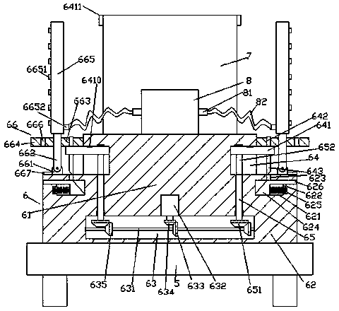
  • Figure 1
    Figure 1
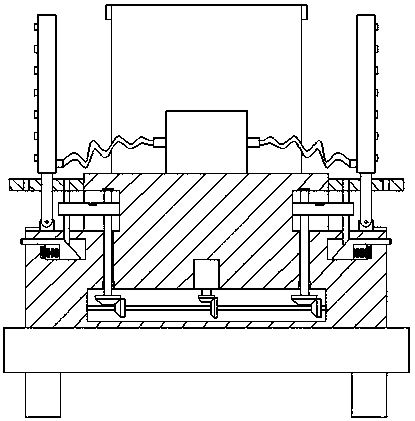
  • Figure 2
    Figure 2
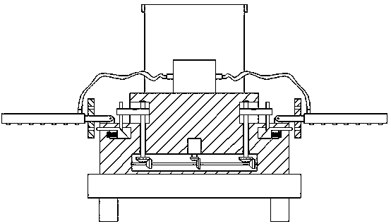
  • Figure 3
    Figure 3
Patent Text Reader

Abstract

The invention discloses a stable pesticide spraying vehicle device of a foldable structure. The device comprises a walking vehicle and a pesticide spraying mechanism fixed to the top of the walking vehicle, the pesticide spraying mechanism is composed of a main rack and sub racks at the left and right sides of the main rack, and a first cavity extending leftwards and rightwards is formed in the main rack; a first rotation shaft which extends leftwards and rightwards is arranged in the first cavity, a motor is embedded in the middle of the top wall in the first cavity, and a first bevel gear which extends into the first cavity is cooperatively connected to the bottom of the motor; a second bevel gear which is fixedly connected with the outer surface of the first rotation shaft in the circumferential direction is meshed with the right side end of the first bevel gear, guide grooves are formed in the left and right end faces of the main rack above the first cavity, and the guide grooves in the left and right sides are formed in the upper portions of the extension segments at the left and right sides of the first cavity respectively. The stable pesticide spraying vehicle device of thefoldable structure is simple in structure and convenient to operate, the running stability of the device is improved, various spraying requirements can be met, the device is convenient to move and transport, and the efficiency of spraying pesticide is improved.
Need to check novelty before this filing date? Find Prior Art

Description

technical field

[0001] The invention relates to the technical field of pesticide spraying machinery, in particular to a pesticide spraying vehicle device with a stable folding structure. Background technique

[0002] During the growth process of crops, due to insect pests or other reasons, pesticides need to be sprayed frequently to promote their growth. The widely used sprayers now mainly include manual sprayers and mechanically driven sprayers. The manual sprayers are carried by people on their backs. , one hand presses the lever to generate pressure, and the other hand holds the nozzle to spray the crops. In the case of a large farmland area and a large workload, it cannot meet the production needs at all. The intensity is particularly high, and it cannot meet the requirements of uniform spraying; with the continuous development of agricultural mechanized production progress, agricultural spraying of pesticides no longer uses manual spraying, but uses mechanical spraying ...

Examples

Embodiment Construction

[0022] like Figure 1-Figure 5 As shown, a stable foldable structure pesticide spraying vehicle device of the present invention includes a traveling cart 5 and a spraying mechanism 6 fixed on the top of the traveling cart 5. The spraying mechanism 6 is composed of a main frame 61 and a set of The main body frame 61 is composed of auxiliary body frames 62 on the left and right sides. The main body frame 61 is provided with a first cavity 63 extending left and right, and the first cavity 63 is provided with a first rotating shaft extending left and right. 631, a motor 632 is embedded in the middle of the inner top wall of the first cavity 63, and a first bevel gear 634 extending into the first cavity 63 is connected to the bottom of the motor 632. The right end of the bevel gear 634 is meshed with a second bevel gear 633 that is circumferentially fixedly connected to the outer surface of the first rotating shaft 631 . Guide grooves 64 are provided, and the guide grooves 64 on t...