Pre-warming device for steel plate pretreatment line

A pretreatment and steel plate technology, which is applied in the field of auxiliary equipment for steel plate pretreatment lines, can solve problems such as waste of production costs, impact on shot blasting, and prolonging preheating time

Inactive Publication Date: 2018-06-29
ZHENJIANG SUBAIXIN CONSTR MACHINERY CO LTD
View PDF0 Cites 0 Cited by
  • Summary
  • Abstract
  • Description
  • Claims
  • Application Information

AI Technical Summary

Problems solved by technology

[0002] The steel plate needs to be preheated before shot blasting to remove surface water, increase the temperature of the steel and achieve the initial effect of oxidation and shedding, so that the rust on the surface of the steel plate can be better removed in the subsequent shot blasting treatment. The existing technology In the shot blasting chamber, a preheating chamber is usually installed in front of the shot blasting chamber, and the preheating chamber is directly used for preheating. The traditional method can contact the steel surface through the burning flame flow, carbonize the surface oil, remove surface water, and improve Steel temperature, but because the preheating temperature does not reach the target, the preheating effect is not good, which affects the subsequent shot blasting treatment. If you want to prolong the preheating time, you have to delay the process of the whole set of equipment, resulting in a waste of production costs

Method used


Image

  • Pre-warming device for steel plate pretreatment line
  • Pre-warming device for steel plate pretreatment line

Examples


Embodiment Construction

[0010] The steel plate pretreatment line preheating device of the present invention will be further described in detail below in conjunction with the accompanying drawings and specific embodiments.

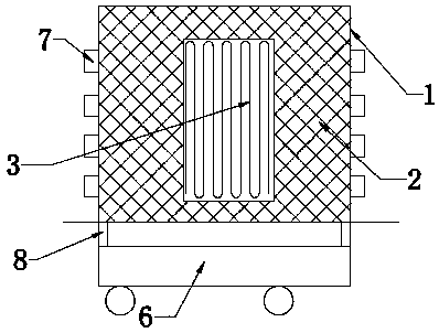
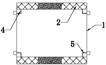
[0011] As shown in the figure, the steel plate pretreatment line preheating device of the present invention includes a preheating room 1 located in front of the preheating room. The left and right side walls of the preheating room 1 are provided with insulation layers 2, and the left and right sides of the preheating room 1 A coil pipe 3 located in the middle of the heat preservation layer is also arranged on the side wall, and the coil pipe 3 can heat and heat the pre-heating chamber through the control device. The guide rail 4 arranged vertically, the steel plate seat 5 that can vertically lift on the guide rail is arranged on the guide rail 4, and the bottom of the preheating room 1 is provided with a mobile trolley 6, and the mobile trolley 6 can output the steel plate after pr...


PUM


Abstract

The invention discloses a pre-warming device for a steel plate pretreatment line. The pre-warming device for the steel plate pretreatment line comprises a pre-warming chamber; the left side wall and the right side wall of the pre-warming chamber are provided a with heat-preserving layer; coil pipes located on the middle portion of the heat-preserving layer are further arranged on the left side wall and the right side wall of the pre-warming chamber, and are controlled by a control device to be capable of warming and heating the pre-warming chamber; four vertically arranged guide rails locatedon the four edge and corner portions of the pre-warming chamber are in the pre-warming chamber, and are provided with a steel plate installing base capable of vertically rising and falling on the guide rails; and a movable trolley is arranged at the bottom of the pre-warming chamber, and can be used for outputting a pre-warmed steel plate. After the structure is adopted, the steel plate can be installed on the installing base to be placed into the pre-warming chamber to be pre-warmed and pre-heated, after certain temperature is achieved, the steel plate is output through the movable trolley and then is conveyed to a pre-heating chamber to be pre-heated, the pre-warmed steel plate can be fast pre-heated in this way, the pre-heating time is shortened, pre-heating indexes are achieved, the production cost is saved, and the subsequent shot blasting effect is guaranteed.

Description

technical field [0001] The invention relates to an auxiliary device for a steel plate pretreatment line, in particular to a preheating device for a steel plate pretreatment line. Background technique [0002] The steel plate needs to be preheated before shot blasting to remove surface water, increase the temperature of the steel and achieve the initial effect of oxidation and shedding, so that the rust on the surface of the steel plate can be better removed in the subsequent shot blasting treatment. The existing technology In the shot blasting chamber, a preheating chamber is usually installed in front of the shot blasting chamber, and the preheating chamber is directly used for preheating. The traditional method can contact the steel surface through the burning flame flow, carbonize the surface oil, remove surface water, and improve Steel temperature, but because the preheating temperature does not reach the target, the preheating effect is not good, which affects the subse...

Claims


Application Information

Patent Timeline
Patent Type & Authority Applications(China)
IPC IPC(8): B24C1/08C21D1/82
CPCB24C1/086C21D1/82
Inventor 张长凤
Owner ZHENJIANG SUBAIXIN CONSTR MACHINERY CO LTD
Why Eureka
Try Eureka