Heat storage system for an engine

a technology for storage systems and engines, applied in indirect heat exchangers, machines/engines, lighting and heating apparatus, etc., can solve the problems of increasing exhaust emissions, the conversion unit does not operate at an efficient temperature, etc., and achieves rapid heating of various engine components. , the effect of reducing the volume of circulating heat transfer fluid

Inactive Publication Date: 2014-08-05
FORD GLOBAL TECH LLC
View PDF20 Cites 7 Cited by
  • Summary
  • Abstract
  • Description
  • Claims
  • Application Information

AI Technical Summary

Benefits of technology

[0004]According to one embodiment, a method for recovering exhaust heat includes reducing a volume of a circulating heat transfer fluid and discharging a heat storage device to heat an engine component. The method further includes, distributing the circulating heat transfer fluid to one or more engine systems. As such, heat may be discharged directly from a heat recovery system and provided to another engine system. Further, the heat storage device may be recharged by reducing the volume of the circulating heat transfer fluid. This configuration enables stored heat from a previous engine operation to be available at engine start to rapidly warm up various engine components.

Problems solved by technology

Further, transferring heat away from the exhaust system during a cold start operation delays the catalytic converter ‘light-off.” As a result, the catalytic converter does not operate at an efficient temperature to burn trapped hydrocarbons, thereby increasing exhaust emissions.

Method used


Image

  • Heat storage system for an engine
  • Heat storage system for an engine
  • Heat storage system for an engine

Examples


Embodiment Construction

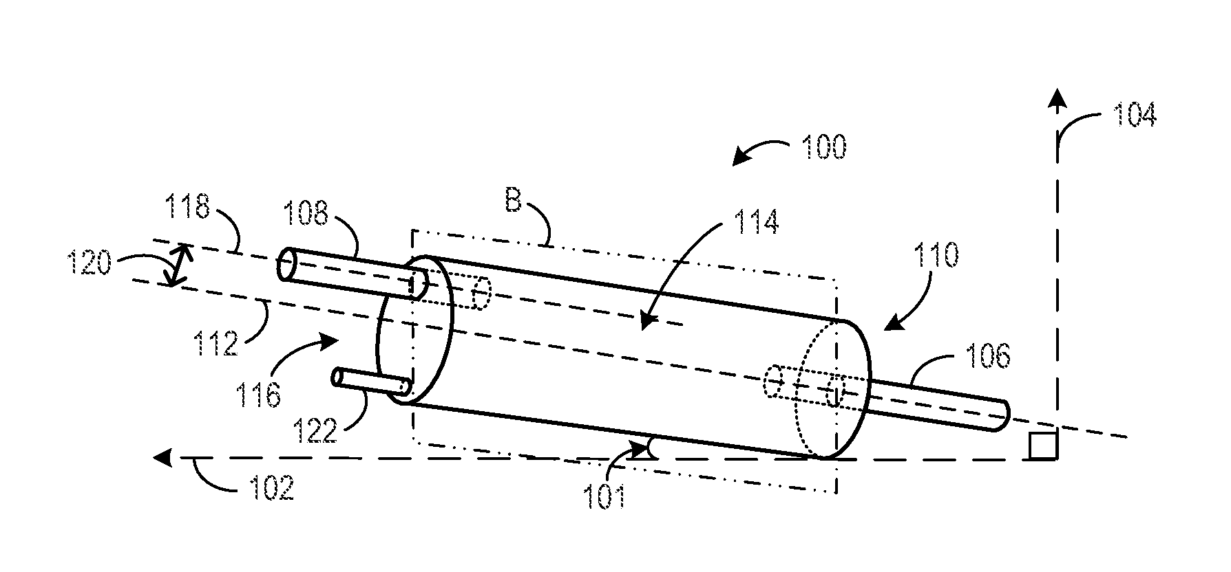
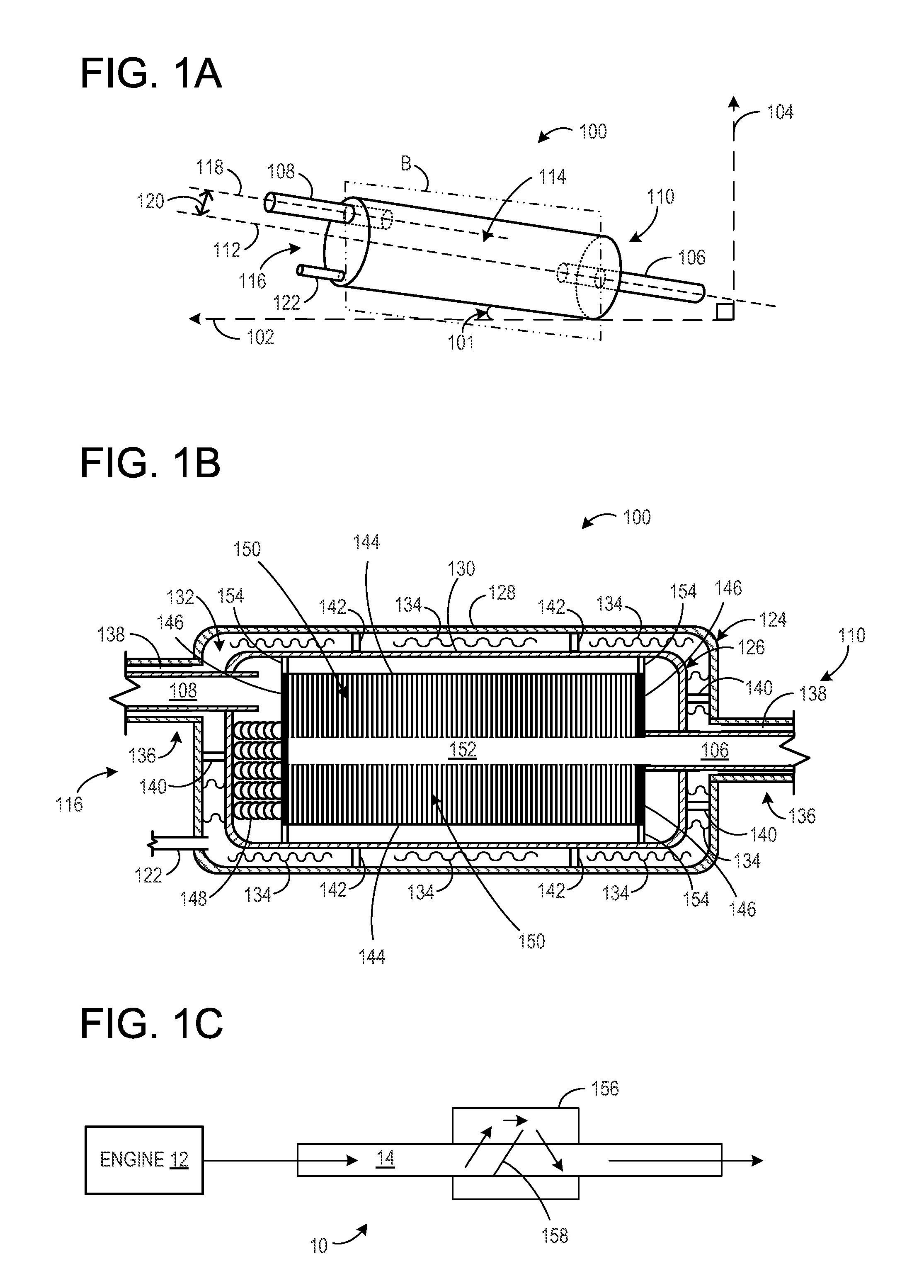
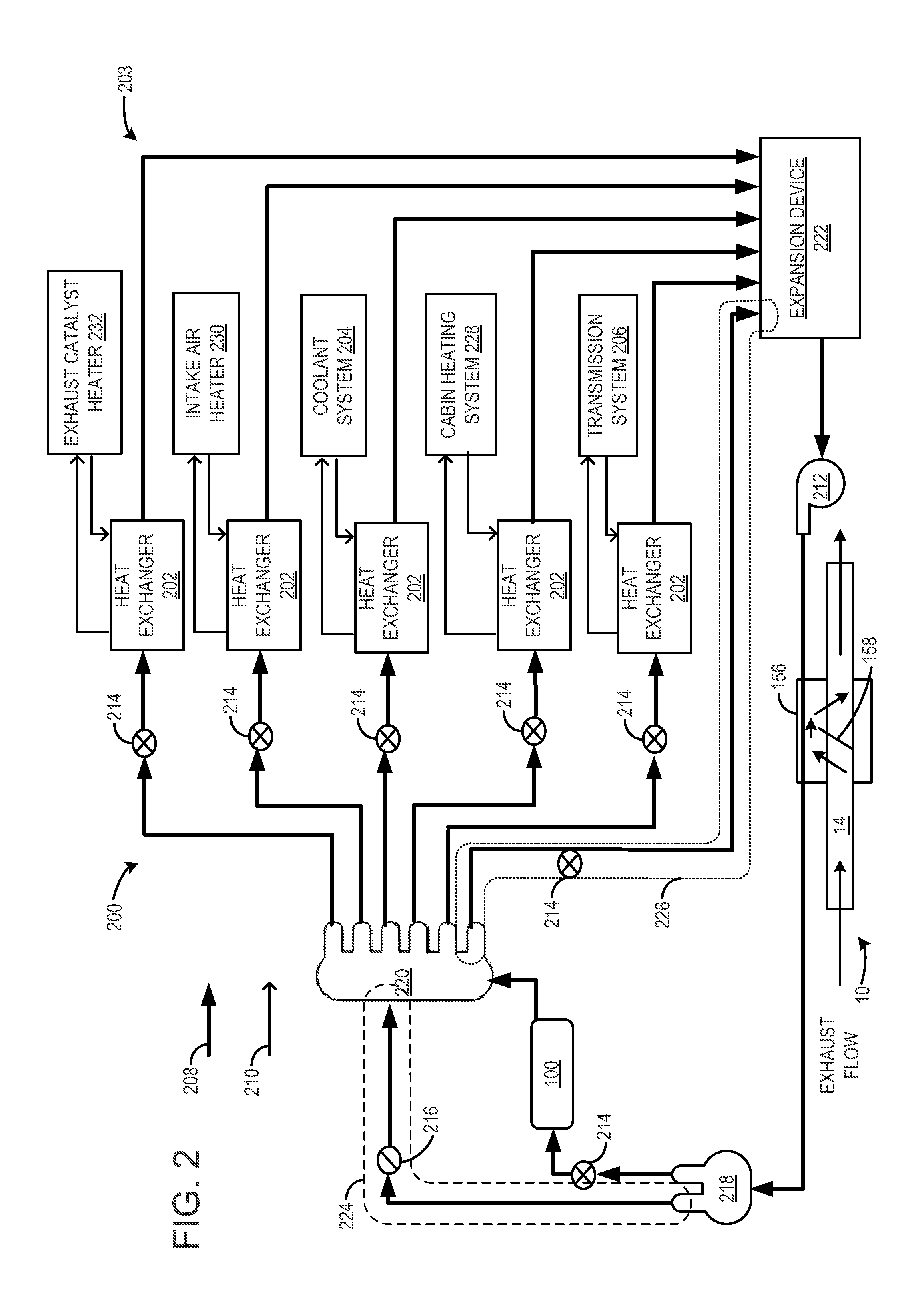
[0010]The following description relates to a heat transfer system including phase changing materials, which are arranged in such a way that thermal energy from an exhaust system can be recovered. The example arrangements described herein allow thermal energy to be recovered and stored for later heating of a passenger compartment, for example. A heat transfer system may utilize a heat storage device to transfer heat even when the engine is not in operation. For example, the heat storage device may be in fluidic communication with an exhaust system component downstream from the catalytic converter, such as via heat exchanger. In this way, heat may transfer from the heat storage device even after the engine is no longer in operation. For example, the heat storage device may be insulated to store heat recovered from the exhaust system, which may be available for immediate use at engine start.

[0011]Additionally, the heat transfer system may include various heat transfer fluids to extract...


PUM


Abstract

A method for recovering exhaust heat for an engine is disclosed herein. The method includes during an engine operation, reducing a volume of a circulating heat transfer fluid and discharging a heat storage device to heat an engine component. The method further includes distributing the circulating heat transfer fluid to one or more heat exchangers each in thermal contact with one or more engine systems.

Description

BACKGROUND AND SUMMARY[0001]Vehicles may recover exhaust heat for transfer to various other systems in an internal combustion engine.[0002]The inventors herein have recognized that rapid heat at engine start is not available in most systems because the systems require the exhaust system to warm up first, before wasted engine heat can be used to heat up various components. Further, transferring heat away from the exhaust system during a cold start operation delays the catalytic converter ‘light-off.” As a result, the catalytic converter does not operate at an efficient temperature to burn trapped hydrocarbons, thereby increasing exhaust emissions.[0003]As such, one example approach to address the above issues is claim 1.[0004]According to one embodiment, a method for recovering exhaust heat includes reducing a volume of a circulating heat transfer fluid and discharging a heat storage device to heat an engine component. The method further includes, distributing the circulating heat tr...

Claims


Application Information

Patent Timeline
Patent Type & Authority Patents(United States)
IPC IPC(8): F01P7/14F01P3/20F01P11/02
CPCF02G5/02B60H1/00492B60H1/20F28D20/02F28D20/023F28D20/028F28D21/0003F28F2250/06Y02E60/145Y02T10/166Y02E60/14Y02T10/12F01P7/14F01P11/02
Inventor LEVIN, MICHAELSHAIKH, FURQAN ZAFARDEMITROFF, DANRICH HENRYMASCH, DONALDO'NEILL, JAMES PATRICK
Owner FORD GLOBAL TECH LLC
Why Eureka
Try Eureka