Dynamic stabilization medical implant assemblies and methods

a technology of medical implants and components, applied in the field of spinal surgery apparatuses and methods, can solve the problems of reducing or eliminating the ability of spinal joints to move in a more normal relation to one another, fusion has failed to provide pain relief, and fusion has some undesirable side effects, etc., to achieve the effect of reducing volume, convenient use and low cos

Inactive Publication Date: 2007-01-18
JACKSON
View PDF16 Cites 285 Cited by
  • Summary
  • Abstract
  • Description
  • Claims
  • Application Information

AI Technical Summary

Benefits of technology

[0013] Therefore, it is an object of the present invention to overcome one or more of the problems with polyaxial bone screw assemblies described above. An object of the invention is to provide dynamic medical implant stabilization assemblies and methods for spinal surgery that include bone screws having an affinity to bone and further include connecting members and / or receiver members that may be removed and replaced to provide for the implantation of flexible, semi-rigid or rigid connecting members. Another object of the invention is to provide dynamic medical implant stabilization assemblies having longitudinal connecting members with portions having various configurations for providing flexible, dynamic stabilization. Additionally, it is an object of the invention to provide a lightweight, reduced volume, low profile polyaxial bone screw and longitudinal connecting member assembly. Furthermore, it is an object of the invention to provide apparatus and methods that are easy to use and especially adapted for the intended use thereof and wherein the tools are comparatively inexpensive to make and suitable for use.
[0014] Other objects and advantages of this invention will become apparent from the following description taken in conjunction with the accompanying drawings wherein are set forth, by way of illustration and example, certain embodiments of this invention.
[0015] The drawings constitute a part of this specification and include exemplary embodiments of the present invention and illustrate various objects and features thereof.

Problems solved by technology

Fusion, however, has some undesirable side effects.
Furthermore, although fusion may result in a strengthened portion of the spine, it also has been linked to more rapid degeneration and even hyper mobility of spinal motion segments that are adjacent to the portion of the spine being fused, reducing or eliminating the ability of such spinal joints to move in a more normal relation to one another.
In certain instances, fusion has also failed to provide pain relief.
However, such devices may be undesirable as they extend upwardly and outwardly from the bone screw or anchor, creating an implant with a profile much larger than those using a traditional cylindrical longitudinal connecting member.
Larger profile implants are almost always undesirable for placement in a human body and may limit the working space afforded to the surgeon during an implant procedure.
The dynamic conditions associated with spinal movement therefore provide quite a challenge for the design of elongate structural members that exhibit an adequate fatigue strength to provide stabilization and protected motion of the spine, without fusion, and allow for some natural movement of the portion of the spine being reinforced by the elongate structural member.

Method used


Image

  • Dynamic stabilization medical implant assemblies and methods
  • Dynamic stabilization medical implant assemblies and methods
  • Dynamic stabilization medical implant assemblies and methods

Examples


Embodiment Construction

[0063] As required, detailed embodiments of the present invention are disclosed herein; however, it is to be understood that the disclosed embodiments are merely exemplary of the invention, which may be embodied in various forms. Therefore, specific structural and functional details disclosed herein are not to be interpreted as limiting, but merely as a basis for the claims and as a representative basis for teaching one skilled in the art to variously employ the present invention in virtually any appropriately detailed structure.

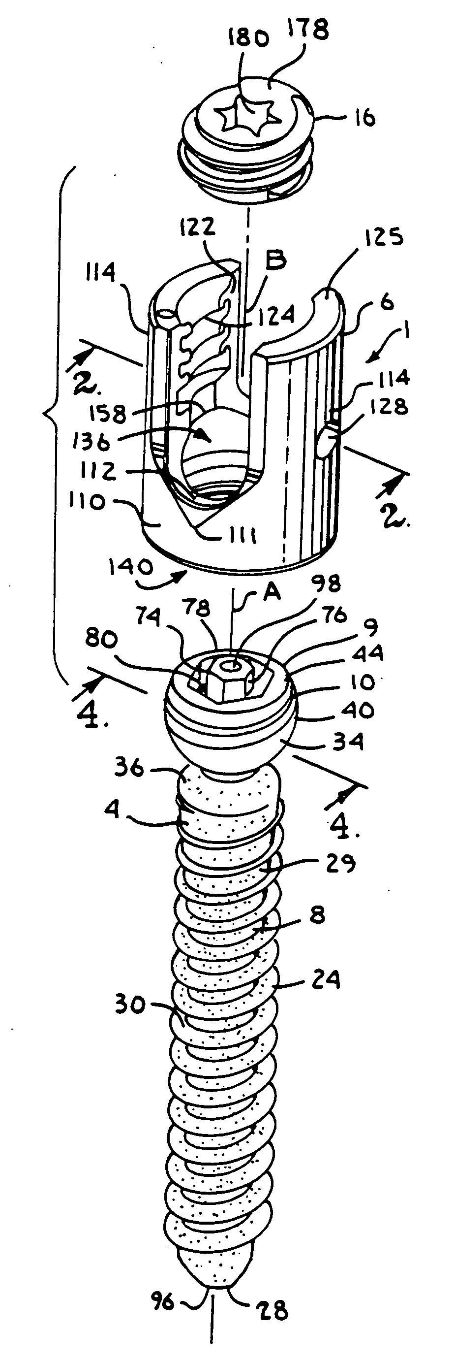
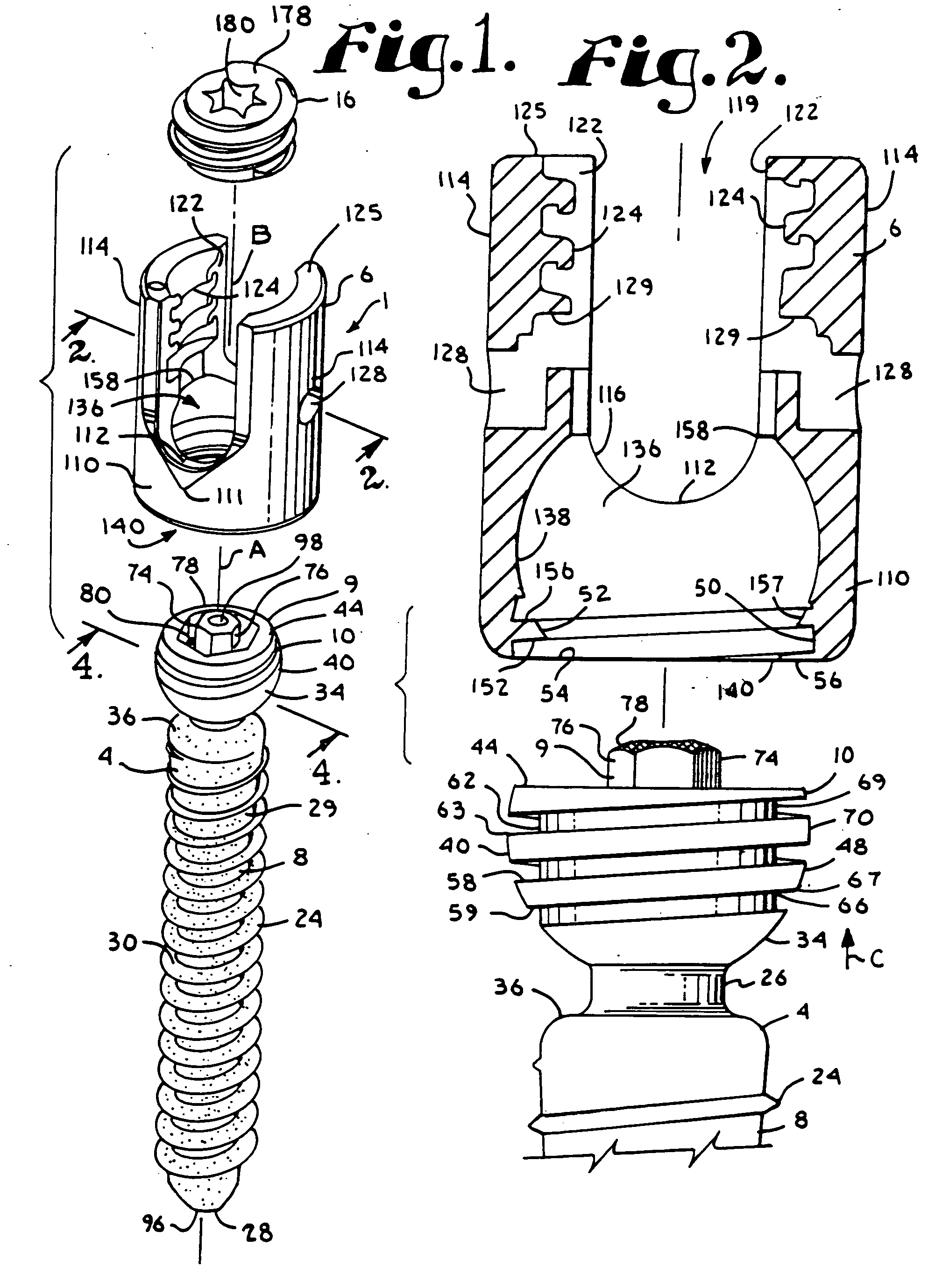
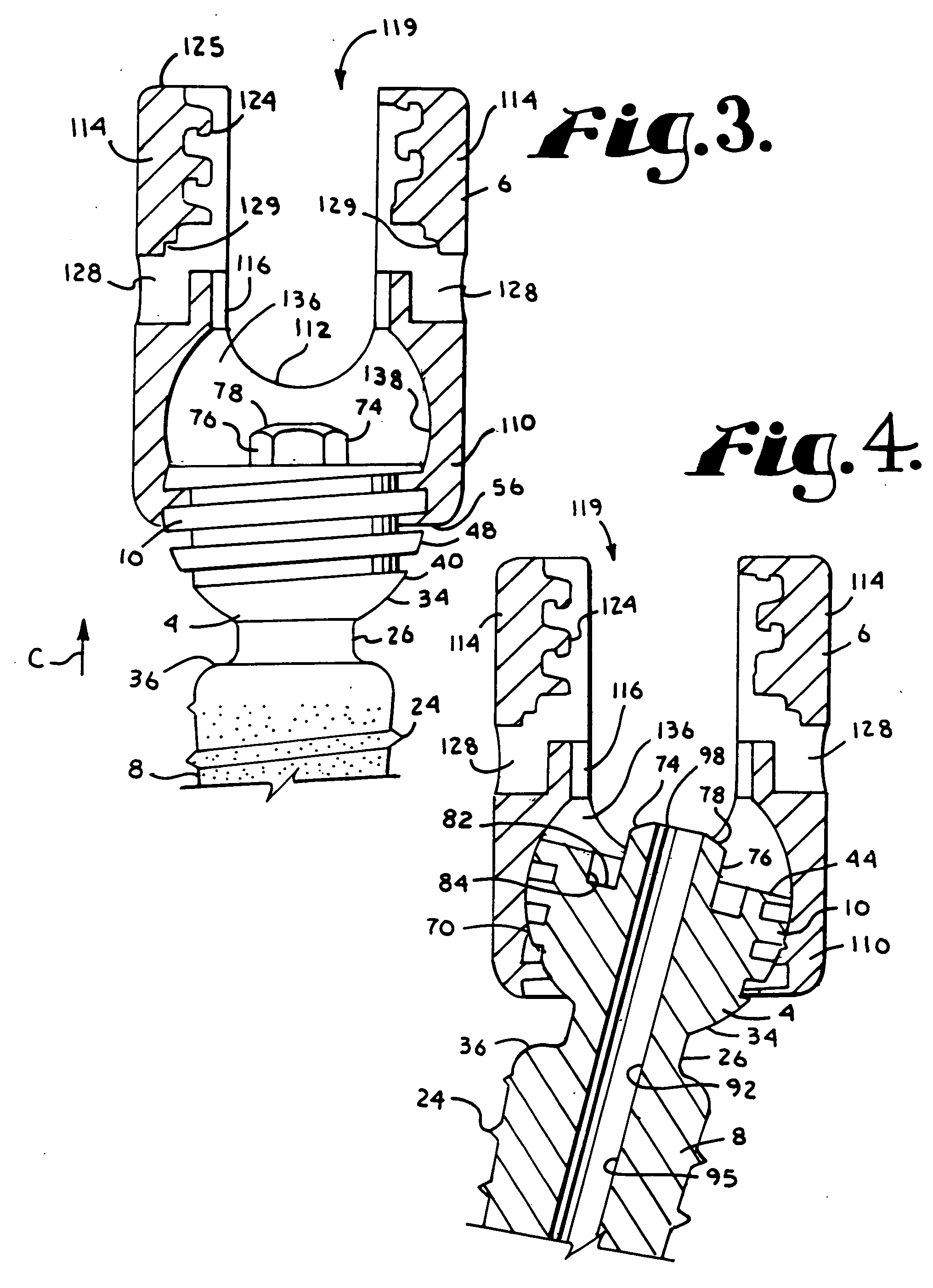
[0064] With reference to FIGS. 1-10, the reference number 1 generally represents a polyaxial bone screw apparatus or assembly according to the present invention. The assembly 1 includes a shank 4, a first receiver 6 and a second or replacement receiver 7. The shank 4 further includes a body 8 integral with an upper portion 9 having a capture structure 10. The shank 4 and the receiver 6 are often assembled prior to implantation of the shank body 8 into a ver...


PUM


Abstract

Bone screw assemblies include longitudinal connecting members that provide for dynamic stabilization, some including non-uniform portions that are configured to flex, contract or expand. Composite longitudinal connecting members include longitudinal segments made from different materials having different flexibilities. Polyaxial bone screw assemblies include change-out receivers for cooperating with replacement longitudinal connecting members having a different flexibility. Bone screw shanks for cooperating with one or more open receivers include treatment or coating to provide biologically active interface with bone.

Description

CROSS-REFERENCE TO RELATED APPLICATIONS [0001] This application claims the benefit of U.S. Provisional Application No. 60 / 722,300 filed Sep. 30, 2005. This application is also a continuation-in-part of U.S. patent application Ser. No. 10 / 958,743 filed Oct. 5, 2004, which is a continuation-in-part of U.S. patent application, Ser. No. 10 / 409,935 filed Apr. 9, 2003, now U.S. Pat. No. 6,964,666. This application is also a continuation-in-part of U.S. patent application Ser. No. 10 / 818,555, filed Apr. 5, 2004, which is a continuation of U.S. patent application Ser. No. 10 / 464,633 filed Jun. 18, 2003, now U.S. Pat. No. 6,716,214. This application is also a continuation-in-part of U.S. patent application Ser. No. 10 / 996,349 filed Nov. 23, 2004.BACKGROUND OF THE INVENTION [0002] The present invention relates to apparatuses and methods for use in performing spinal surgery and, in particular, to structural members for use in spinal surgery including dynamic stabilization longitudinal connecti...

Claims


Application Information

Patent Timeline
Patent Type & Authority Applications(United States)
IPC IPC(8): A61F2/30
CPCA61B17/7004A61B17/7005A61B17/7026A61B17/7031A61B17/7082A61B17/7037A61B17/8625A61B2019/307A61F2/0077A61B17/7032A61B2090/037A61B17/7091A61B17/7002A61B17/7011A61B17/7085
Inventor JACKSON
Owner JACKSON
Why Eureka
Try Eureka