Exhaust heat regenerator for vehicle
a heat accumulator and vehicle technology, applied in the direction of machines/engines, engine starters, lighting and heating apparatus, etc., can solve the problems of small increment in the temperature of coolant, small effect on engine warm-up performance improvement, large energy loss, etc., to achieve rapid heat exchange, enhance heat accumulation performance and heat exchange performance of heat accumulators, and reduce fuel consumption at the initial stage of engine star
- Summary
- Abstract
- Description
- Claims
- Application Information
AI Technical Summary
Benefits of technology
Problems solved by technology
Method used
Image
Examples
first embodiment
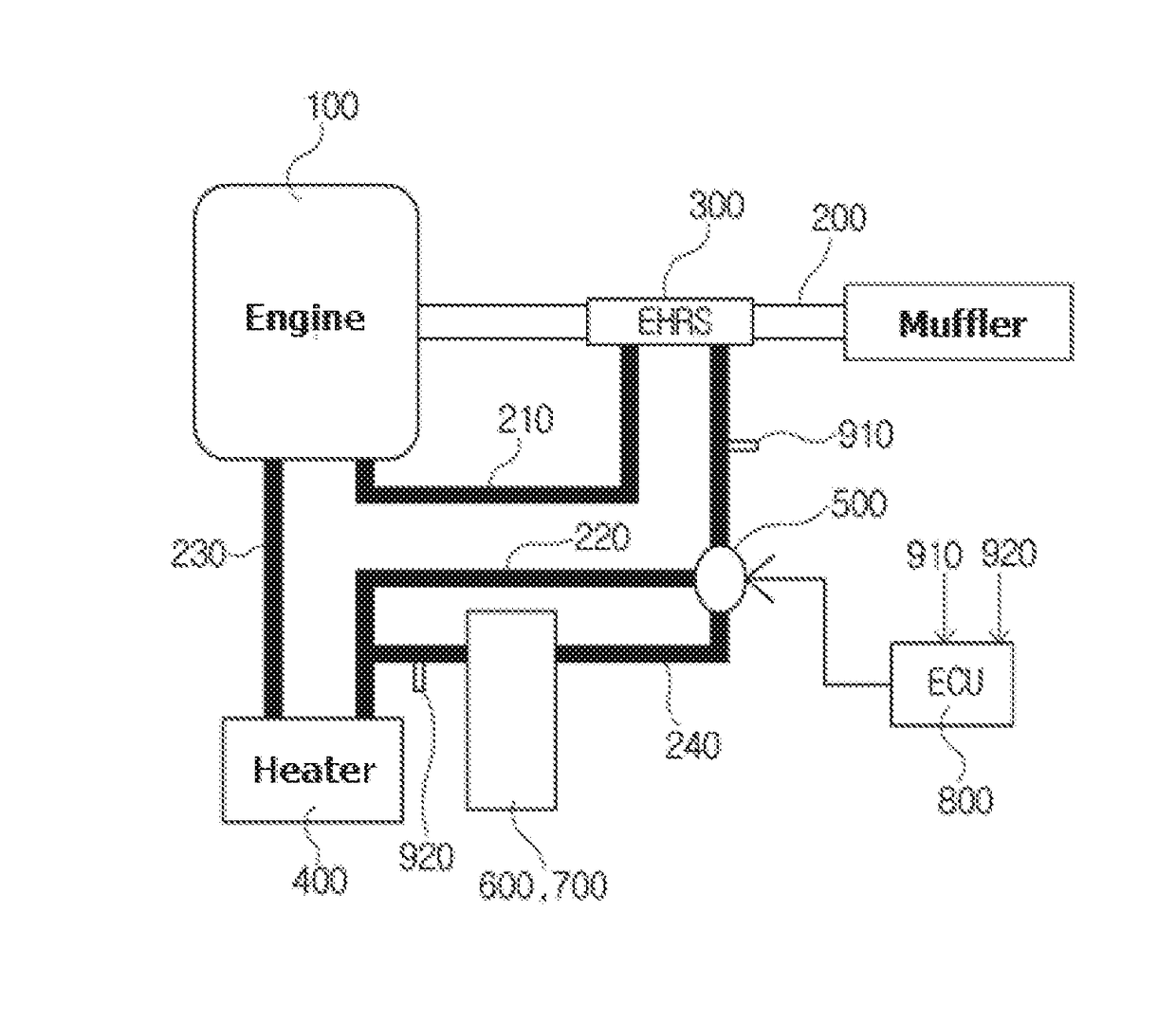
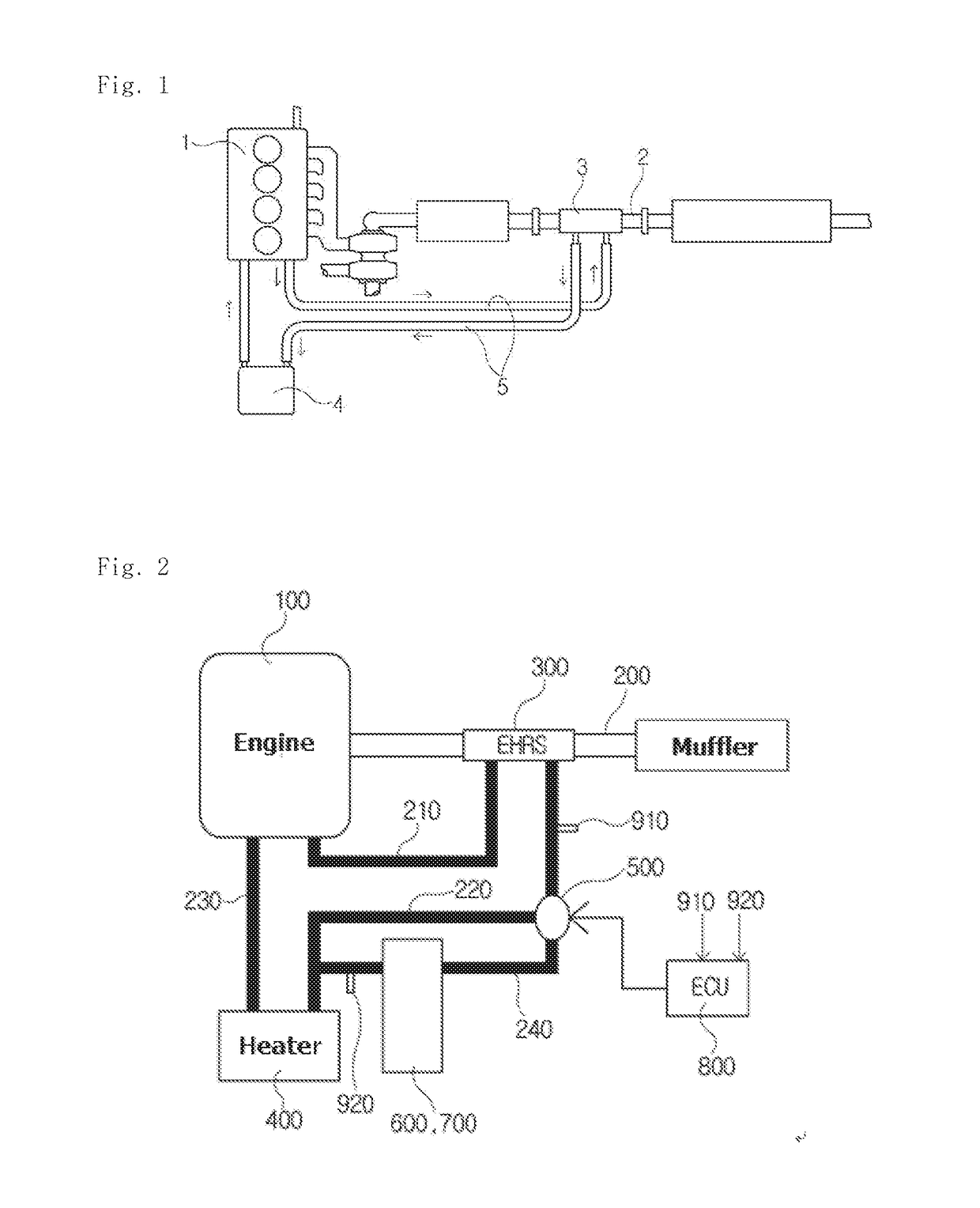
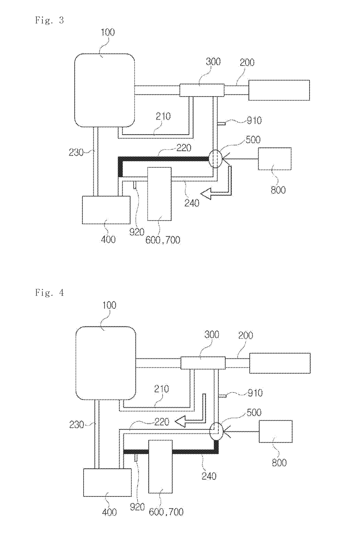
[0090]As shown in FIGS. 6 and 7, the heat accumulator 600 installed in the exhaust heat regenerator for vehicles according to the present invention includes an accumulation heat exchanger 610 through which coolant discharged from the exhaust-heat-recovery heat exchanger 300 passes, an inner casing 620 which encloses the accumulation heat exchanger 610 with a space between it and the heat exchanger 610, and an outer casing 630 which encloses the inner casing 620 with a space between it and the inner casing 620.
[0091]The heat exchanger 610 includes an inlet port 611 and an outlet port 612 on both sides of an upper surface thereof. The inlet port 611 and the outlet port 612 are respectively coupled to both ends of the heat accumulator 600 of the coolant bypass pipe 240, thus forming a coolant path which passes through the accumulation heat exchanger 610.
[0092]A heat storage material injection port 621 is formed on a central portion of an upper surface of the inner casing 620.
[0093]The ...
second embodiment
[0104]FIG. 8 is an exploded perspective view illustrating the configuration of a heat accumulator installed in the exhaust heat regenerator for vehicles according to the present invention. As shown in the drawing, the heat accumulator 700 of the exhaust heat regenerator for vehicles according to the present embodiment includes a heat exchanger 710 through which coolant passes, an inner casing 720 in which the heat exchanger 710 is housed, a heat storage material which is charged into space between the heat exchanger 710 and the inner casing 720, an outer casing 740 which houses the inner casing 720, and an insulation space which is formed between the inner casing 720 and the outer casing 740.
[0105]As shown in FIG. 9, the heat exchanger 710 is configured by stacking a plurality of planar tubes 711. The heat exchanger 710 is manufactured in a cylindrical shape so as to minimize a heat exchange area between it and the outside in an insulated state. Therefore, each of the planar tubes 7...
PUM
 Abstract
Description
Claims
Application Information
 - R&D
- Intellectual Property
- Life Sciences
- Materials
- Tech Scout
- Unparalleled Data Quality
- Higher Quality Content
- 60% Fewer Hallucinations
Browse by: Latest US Patents, China's latest patents, Technical Efficacy Thesaurus, Application Domain, Technology Topic, Popular Technical Reports.
© 2025 PatSnap. All rights reserved.Legal|Privacy policy|Modern Slavery Act Transparency Statement|Sitemap|About US| Contact US: help@patsnap.com


