Oil-cooled cylinder block with water-cooled bridge

a technology of oil-cooled cylinder blocks and water-cooled bridges, which is applied in the direction of liquid cooling, cylinders, engine cooling apparatus, etc., can solve the problems of reducing the efficiency of heat removal, system not allowing a different degree of cooling, adversely affecting engine performance, etc., to improve fuel economy, reduce engine heat, the effect of increasing the temperature of the engin

Active Publication Date: 2015-12-17
FORD GLOBAL TECH LLC
View PDF2 Cites 7 Cited by
  • Summary
  • Abstract
  • Description
  • Claims
  • Application Information

AI Technical Summary

Benefits of technology

[0005]Thus in one example, the above issues may be at least partially addressed by a method, comprising: cooling a cylinder head with a first coolant; cooling a cylinder block with a second coolant, the second coolant a different liquid than the first coolant; and cooling a plurality of bore bridges with the first coolant while maintaining separation between the passages containing the first and second coolants, the plurality of bore bridges in between adjacent cylinders of the cylinder block. In this way, the cylinder head and cylinder block are cooled with separately-maintained cooling systems while a portion of the first coolant (e.g., water) of the cylinder head may aid in cooling certain portions of the cylinder block, in particular the bore bridges.
[0006]When a vehicle is first turned on, it may be desirable to rapidly increase the temperature of the engine in order to improve fuel economy. While a water-cooled cylinder block may most effectively remove heat from the engine, a more-than-desired amount of heat may be removed. Alternatively, an oil-cooled cylinder block may remove heat less rapidly than the water-cooled cylinder block, but localized high-temperature regions may exist that adversely affect engine performance. The regions may include the portions in between cylinders known as bore bridges. In some examples, the oil-cooled cylinder block with water-cooled bore bridges may allow the engine to rapidly warm-up while providing sufficient cooling to the bore bridges via the water passages with water from the cylinder head.

Problems solved by technology

However, the inventors herein have identified potential issues with the approach of U.S. Pat. No. 8,555,825.
First, while the cooling passages proposed by Lenz et al. allow fluidic communication between the cylinder block and cylinder head, only a single coolant may be routed through the cooling passages.
The system does not allow a different degree of cooling to be provided by a different coolant in a particular area of the cylinder block / head assembly.
Furthermore, coolant from the coolant jacket surrounding the cylinders may have a high temperature before entering the cooling slot in the bridges as well as the areas proximate to the intake / exhaust valves, thereby decreasing the efficiency of heat removal.
Alternatively, an oil-cooled cylinder block may remove heat less rapidly than the water-cooled cylinder block, but localized high-temperature regions may exist that adversely affect engine performance.

Method used


Image

  • Oil-cooled cylinder block with water-cooled bridge
  • Oil-cooled cylinder block with water-cooled bridge
  • Oil-cooled cylinder block with water-cooled bridge

Examples


Embodiment Construction

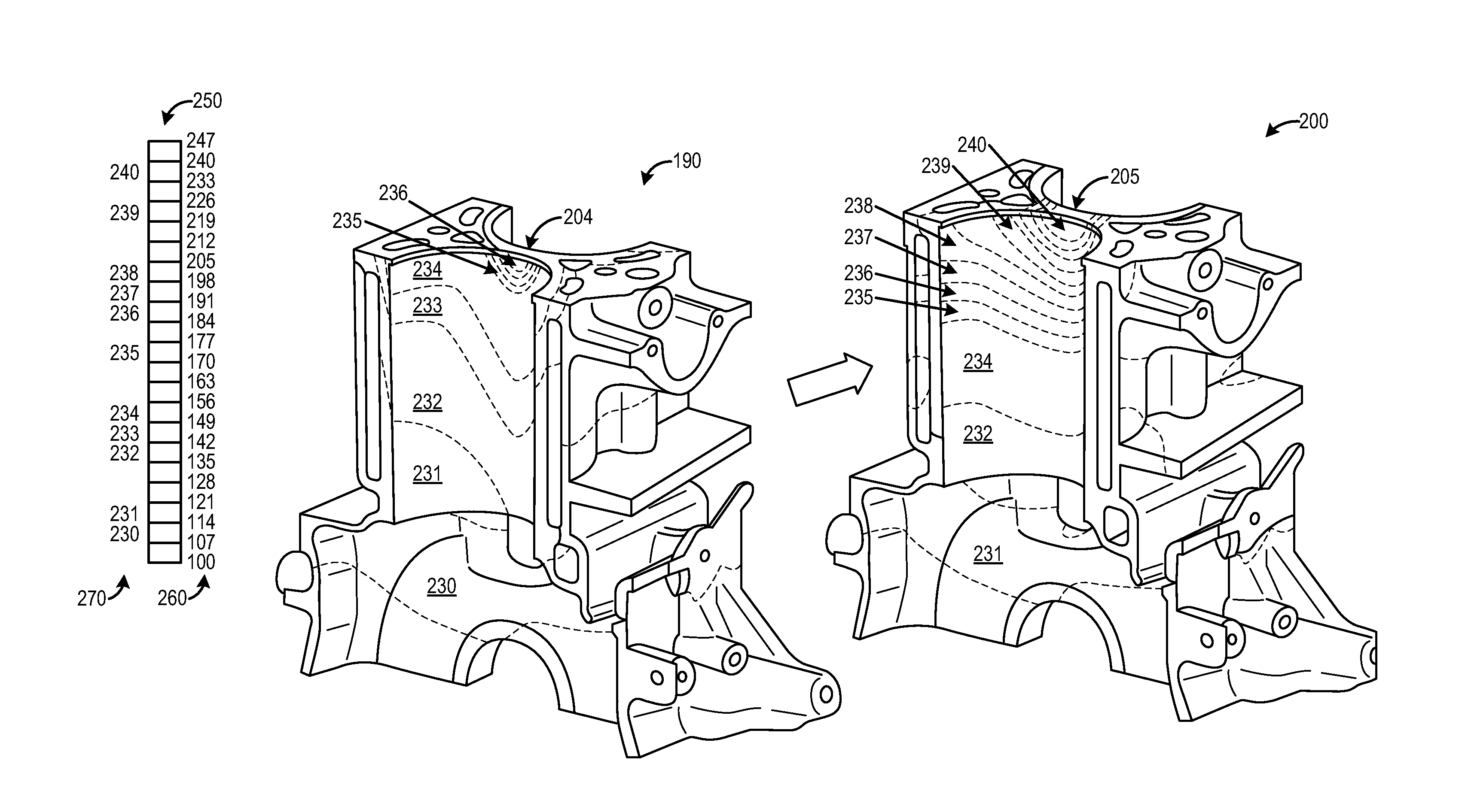
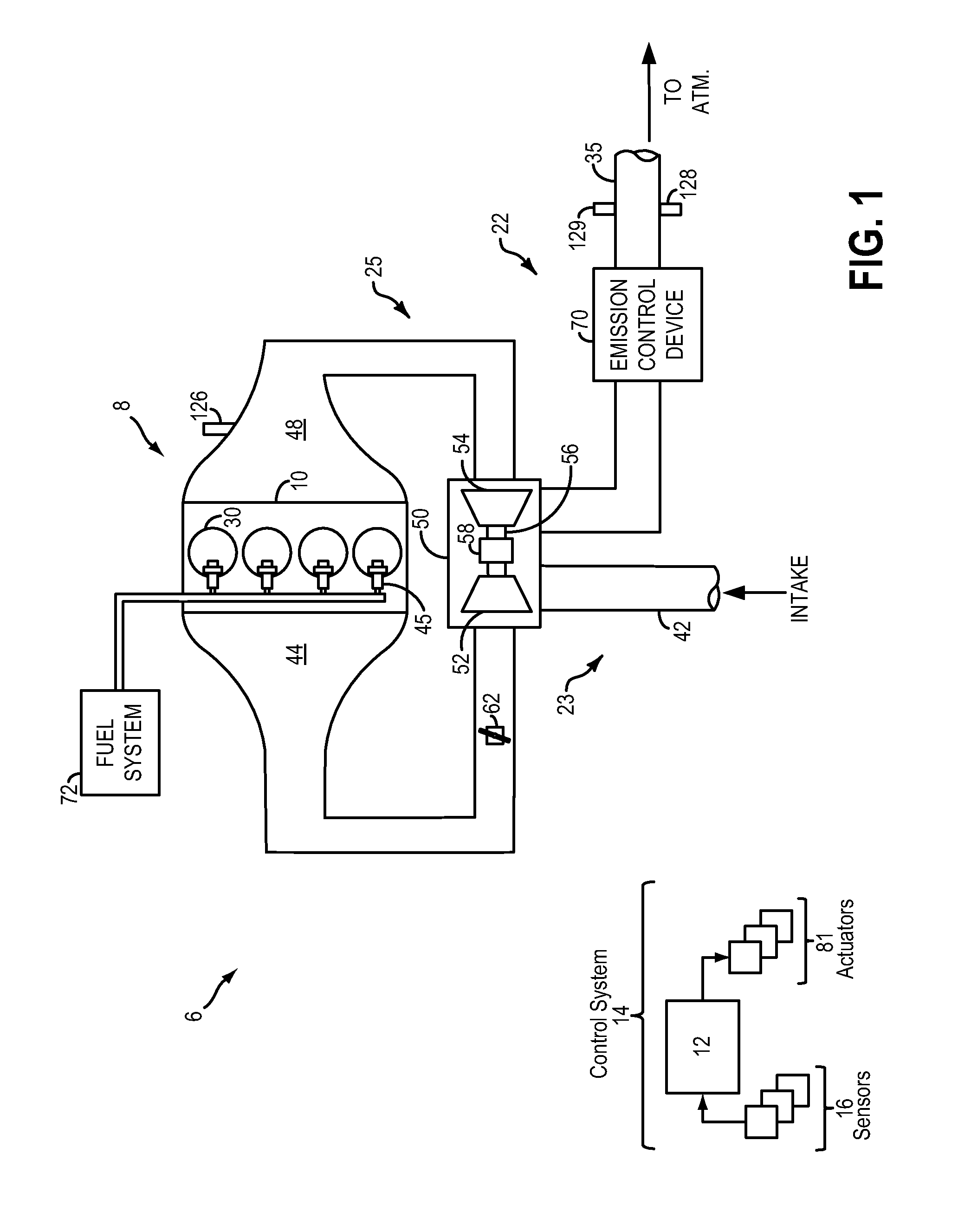
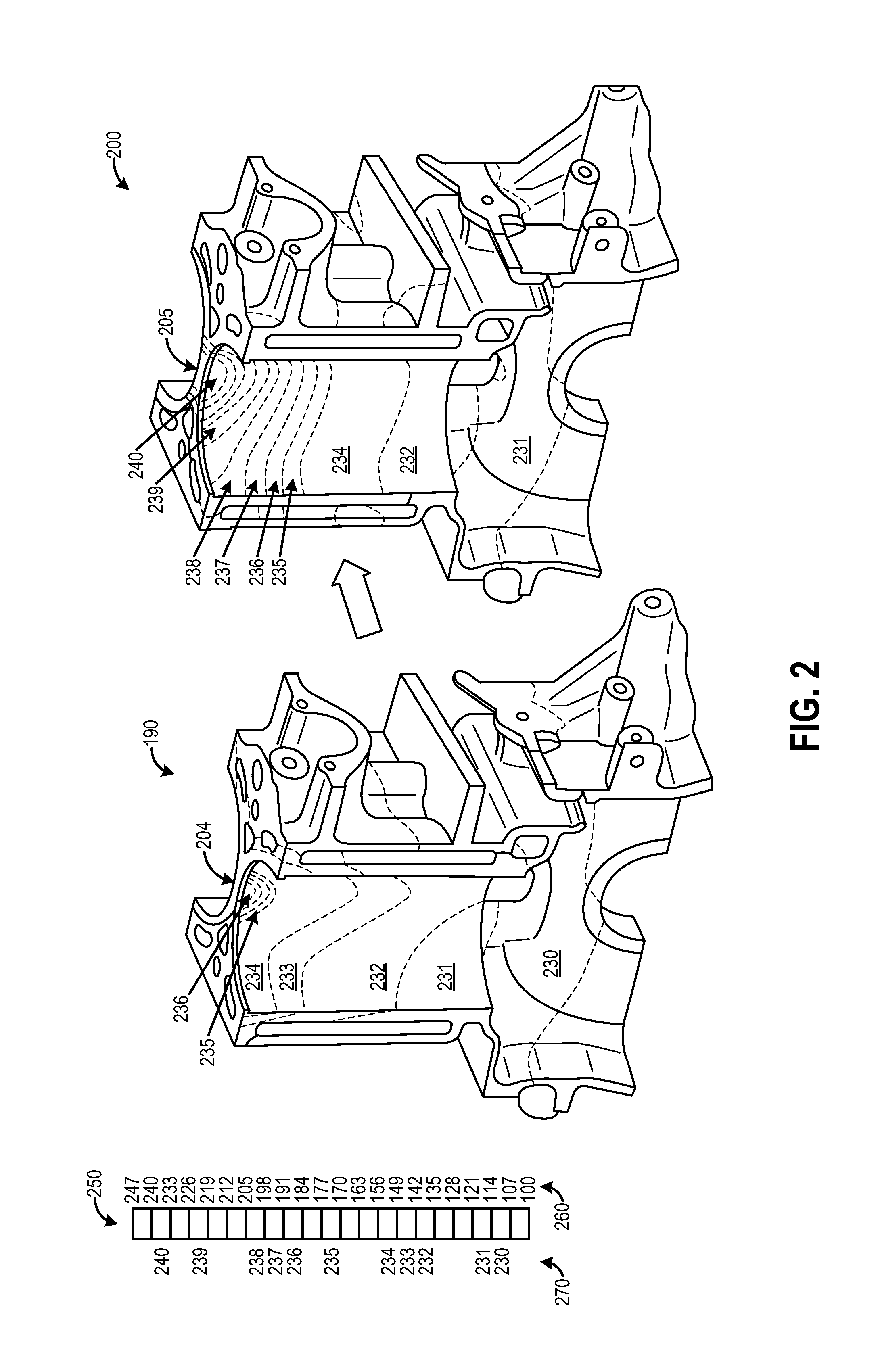
[0016]The following detailed description provides information regarding an oil-cooled cylinder block with a water-cooled cylinder head and their associated components. A simplified schematic diagram of a vehicle system is shown in FIG. 1. FIG. 2 shows an oil-cooled cylinder block and a water-cooled cylinder block with respective temperature gradients showing temperature when the engine is running FIGS. 3 and 4 show a bore bridge of a cylinder block with a cross-drilled passage. FIGS. 5 and 6 show another embodiment of the cross-drilled passage, wherein the cylinder block has a closed deck design. Finally, FIGS. 7 and 8 show yet another embodiment of the cross-drilled passage, wherein the cylinder block has an open deck design.

[0017]FIG. 1 shows a schematic depiction of a vehicle system 6 with a turbocharger. The vehicle system 6 includes an engine system 8 coupled to an exhaust after-treatment system 22. The engine system 8 may include an engine 10 having a plurality of cylinders 30...


PUM


Abstract

Systems are provided to providing water to the bore bridges of a cylinder block that contains an oil cooling system. An oil-cooled cylinder block may be desirable to aid in rapidly increasing engine temperature during engine warm-up, but high local temperatures may exist in the bore bridges in between adjacent cylinders, thereby leading to adverse performance. To control the high local temperatures while maintaining rapid engine warm-up, systems are proposed to provide water coolant from the cylinder head into cross-drilled passages located in the bore bridges of the cylinder block while cooling the rest of the cylinder block with oil or a different coolant.

Description

FIELD[0001]The present application relates generally to a cylinder block, an attached cylinder head, and cooling passages for providing effective cooling to all parts of the cylinder block and head.SUMMARY / BACKGROUND[0002]Engine systems often comprise a cylinder block with an attached cylinder head that include a series of cylinders with surrounding material for attaching various components. Cylinder blocks and cylinder heads also include cooling systems that comprise a number of cooling passages that surround the cylinders. A coolant, such as water, oil, glycol, etc., may be pumped or otherwise sent through the cooling passages to remove heat from the cylinders and cylinder block and head via heat exchange. The cooling passages may include inlets and outlets such that coolant at a lower temperature is directed into the cylinder block and head while coolant at a higher temperature is exited from the cylinder block to a heat exchanger or other device. As such, the temperature of the ...

Claims


Application Information

Patent Timeline
Patent Type & Authority Applications(United States)
IPC IPC(8): F01P3/02
CPCF01P3/02F01P2003/021F01P2003/024F01P2003/008F02F1/14F02F1/36F02F2001/104
Inventor WILLIAMS, RICK L.ULREY, JOSEPH NORMAN
Owner FORD GLOBAL TECH LLC
Why Eureka
Try Eureka