[0004] A
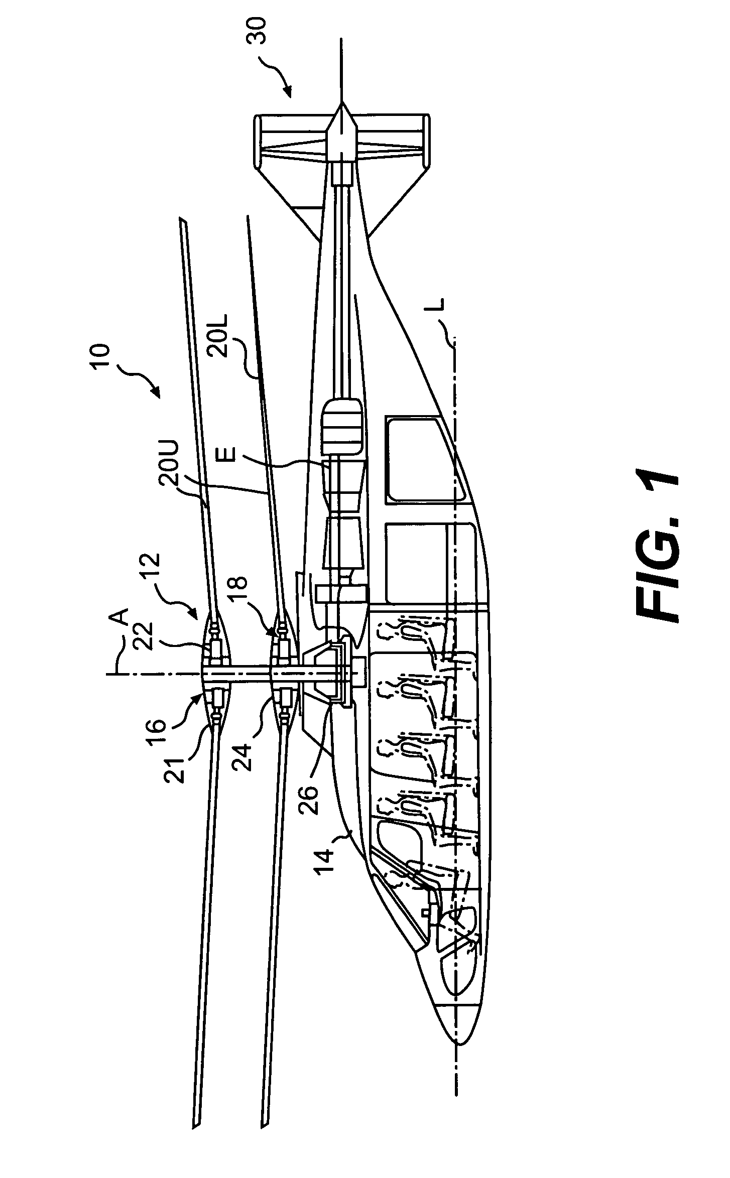
rotary wing aircraft with a coaxial (or other) counter-rotating
rigid rotor system is capable of higher speeds compared to single rotor helicopters due in part to the balance of lift between the advancing sides of the main rotor blades on the upper and lower rotor systems. In addition, the retreating sides of the rotors are also generally free from classic retreating blade stall that conventional single or dual rotor helicopters may suffer from because they are not required to produce lift.
[0005] To still further increase
airspeed, such a
rotary wing aircraft may incorporate an auxiliary translational propulsion system. Use of a rigid coaxial counter-rotating rotor system in combination with an auxiliary translational propulsion system, allows such a rotary-wing aircraft to attain significantly greater speeds than conventional rotary-wing aircraft, while maintaining hover and
low speed capabilities.
[0006] One system significant to these flight attributes is the design of the main rotor system of which the rotor blades are the primary force and moment generating components. Design requirements for a rotary-wing aircraft incorporating a rigid counter-rotating rotor system differ significantly from conventional rotary-wing aircraft. As with a conventional rotary-wing aircraft, the advancing blades of both the upper and lower rotors produce lift; however, unlike a conventional single or multi-rotor rotary-wing aircraft, the retreating blades of the counter-rotating rotor are off-loaded commensurate with increasing
flight velocity, and need not produce lift to balance lateral (rolling) moments. Rather, roll equilibrium is attained by balancing the net effects of the equal and opposite moments produced by the advancing side blades of the counter-rotating rotors. The ability to off-load the retreating blades from producing lift alleviates retreating blade stall—a primary cause of speed limitation on conventional
rotary wing aircraft—thereby permitting much greater forward flight speeds to be achieved.
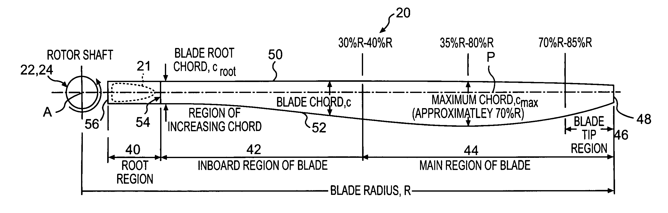
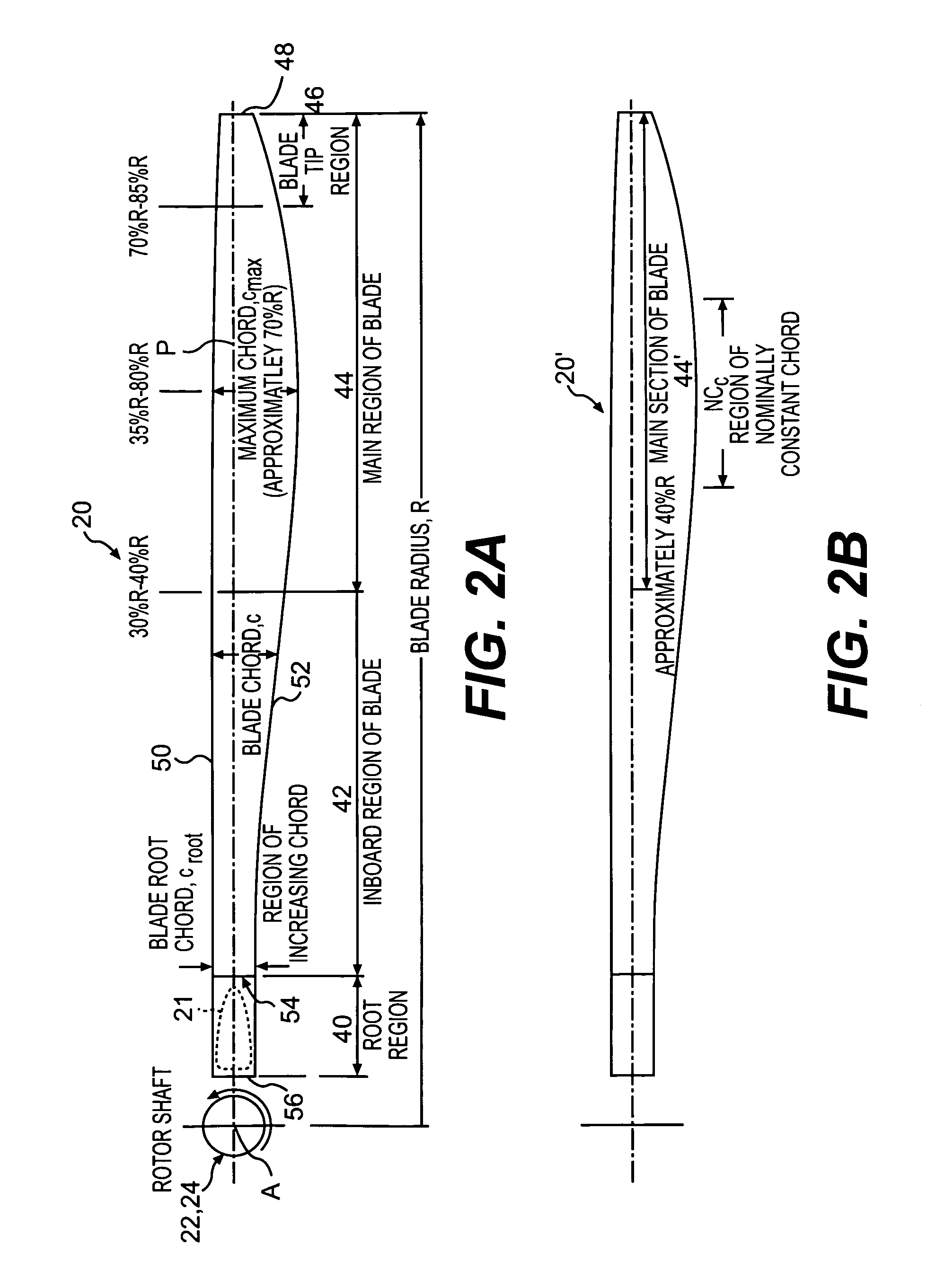
[0010] A main rotor blade of a dual, counter-rotating, coaxial rotor system according to the present invention includes several geometric characteristics, including blade
planform (chord), thickness, airfoil, and twist distributions. The design is an outcome of optimizing rotor performance and flight efficiency, while satisfying structural and aeroelastic requirements throughout an anticipated
flight envelope. The main considerations of the blade design are: a) minimizing drag due to advancing side
compressibility effects at the blade tips, b) reducing retreating side blade drag (over the reversed flow region), c) designing the rotor with sufficient blade area (
solidity), d) maintaining blade aeroelastic stability and, e) maintaining blade tip separations between the upper and lower rotors.
[0011] Advancing side
compressibility effects are minimized through the selection of airfoils, thickness distribution, twist, blade sweep and
rotor speed scheduling with
flight velocity. Retreating side blade drag in reversed flow is minimized by the redistribution of blade chord from inboard regions to outer spanwise locations, twist tailoring and incorporating particular airfoils designed to minimize drag under reversed flow conditions. Blade area (rotor
solidity) maximizes operating design point
performance efficiency while maintaining sufficient maneuver margin. The design parameters are defined to ensure that blade aeroelastic and
tip clearance requirements are satisfied as ascertained from independent structural-dynamic and aeroelastic analyses, while addressing manufacturing considerations.
[0012] The main rotor blades of the dual, counter-rotating, coaxial rotor system exhibit a unique unconventional combination of positive and negative twist gradients and may incorporate dissimilar twist distributions (rates) between the blades of the upper and lower rotors. The rotor system performance is improved by providing a dissimilar twist distribution between the lower rotor blades and the upper rotor blades, resulting in significant improvements in rotor hover efficiency (
Figure of Merit). This improvement is a result of reduced profile drag of the lower rotor system, achieved by driving the effective operating condition of the lower rotor blades to be similar to the upper rotor blades such that the tip drag losses of the lower rotor blades have been reduced considerably. Minimal change in induced
power consumption resulted from the dissimilar lower main rotor twist. Furthermore, improvements in hover efficiency were achieved with little compromise of rotor forward flight performance.

