Expandable interspinous process spacer with lateral support and method for implantation

a technology of interspinous process and spacer, which is applied in the field of devices for treating spinal stenosis, can solve the problems of facet joint breakage, back and leg pain, and the deterioration of the cushioning disc between the vertebrae, so as to relieve the pressure on the posterior wall, relieve pain, and relieve the effect of pain

Active Publication Date: 2009-08-27
ZIMMER GMBH
View PDF51 Cites 41 Cited by
  • Summary
  • Abstract
  • Description
  • Claims
  • Application Information

AI Technical Summary

Benefits of technology

[0011]The present invention addresses these and other problems associated with the prior art by providing a customized interspinous process spacer and associated method to insert it into a medical patient. The interspinous process spacer is to act as a spacing device for the spinous processes of two adjacent vertebrae. The interspinous process spacer is used to distract the vertebrae and relieve pressure on the posterior wall of the intervertebral disc. Furthermore, the interspinous process spacer is expected to relieve pain associated with the spinal canal and / or neural foramen stenosis, as well as potentially relieving pain associated with degenerative facet joints. The interspinous process spacer of the present invention will allow controlled flexion and limited extension at the implanted level.
[0013]In some embodiments of the invention, the medial portion may include a rigid medial member positioned between the superior and inferior spinous processes to maintain separation therebetween. The rigid member may be tubular in shape. In this instance, the medial portion may further comprise an expandable medial member, either positioned within the hollow portion of the tubular rigid medial member, or positioned surrounding the tubular rigid medial member. Alternatively, the expandable lateral portions may be connected to the rigid medial member with no expandable medial member. In any of these embodiments, the opposing lateral portions reside outside the rigid medial member and assist in maintaining the position of the interspinous process spacer. In yet another alternative embodiment, the opposing lateral portions and the medial portion are formed by expandable members, with no rigid medial member.

Problems solved by technology

With lumbar spinal stenosis, the spinal canal narrows and pinches the spinal cord and nerves, causing pain in the back and legs.
The cushioning discs between the vertebrae also frequently deteriorate, and the facet joints may begin to break down.
Over time, loss of disk height in the lumbar regions can result in a degenerative cascade with deterioration of all components of a motion segment resulting in segment instability and ultimately in spinal stenosis.
During the process of deterioration, disks can become herniated and / or become internally torn and chronically painful.
When symptoms seem to emanate from both anterior (disk) and posterior (facets and foramen) structures, patients cannot tolerate positions of extension or flexion.
In extreme cases, spinal stenosis can cause cauda equina syndrome, a syndrome characterized by neuromuscular dysfunction that may result in permanent nerve damage.
Medications such as NSAIDS and other anti-inflammatory medications are often used to alleviate pain, although they are not typically effective at addressing the cause of the pain.
In some procedures, less invasive techniques are advantageous because they have shorter recovery periods, result in little to no blood loss, and greatly decrease the chances of significant complications.

Method used


Image

  • Expandable interspinous process spacer with lateral support and method for implantation
  • Expandable interspinous process spacer with lateral support and method for implantation
  • Expandable interspinous process spacer with lateral support and method for implantation

Examples


Embodiment Construction

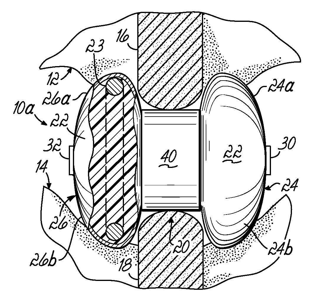
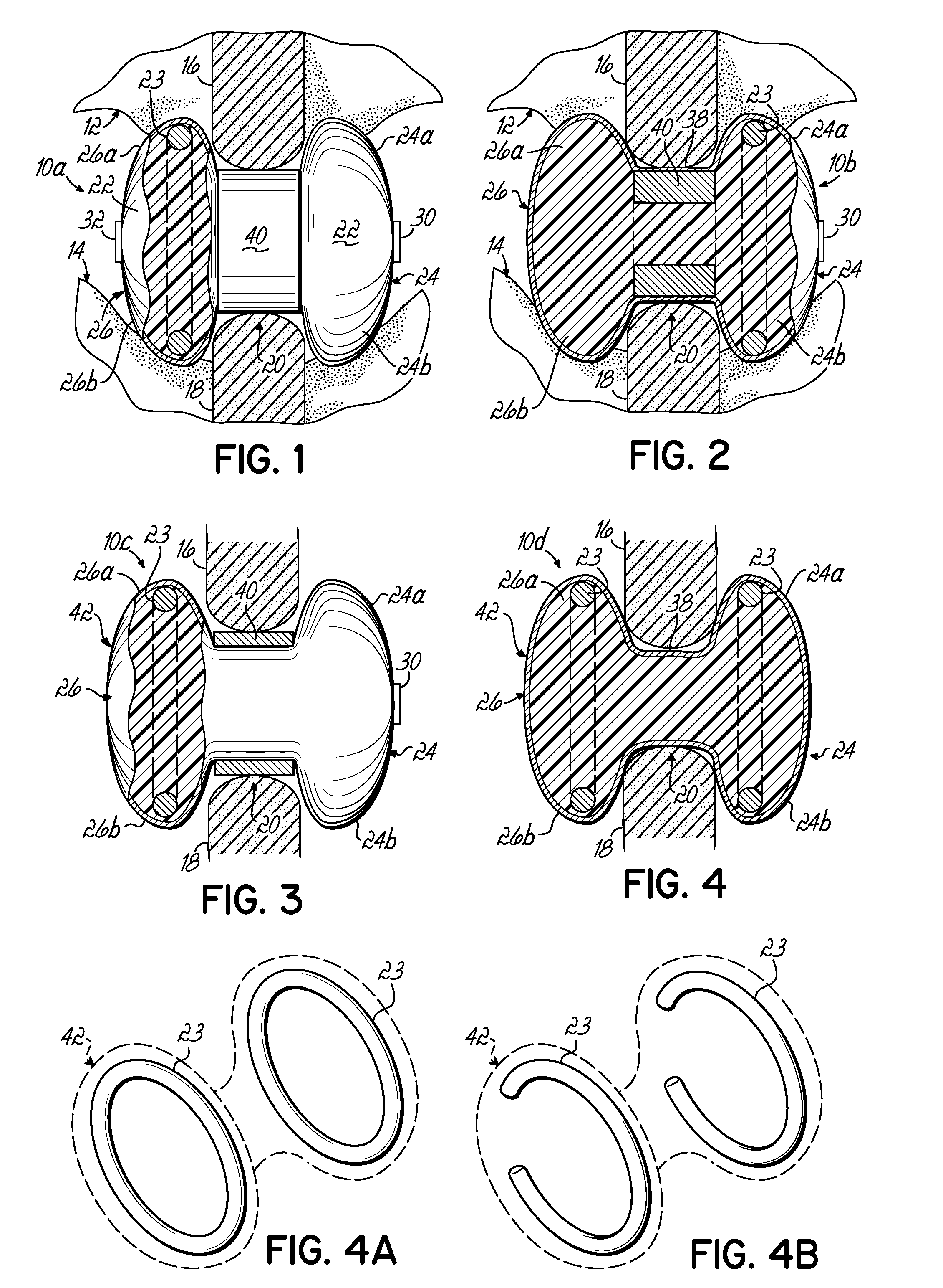
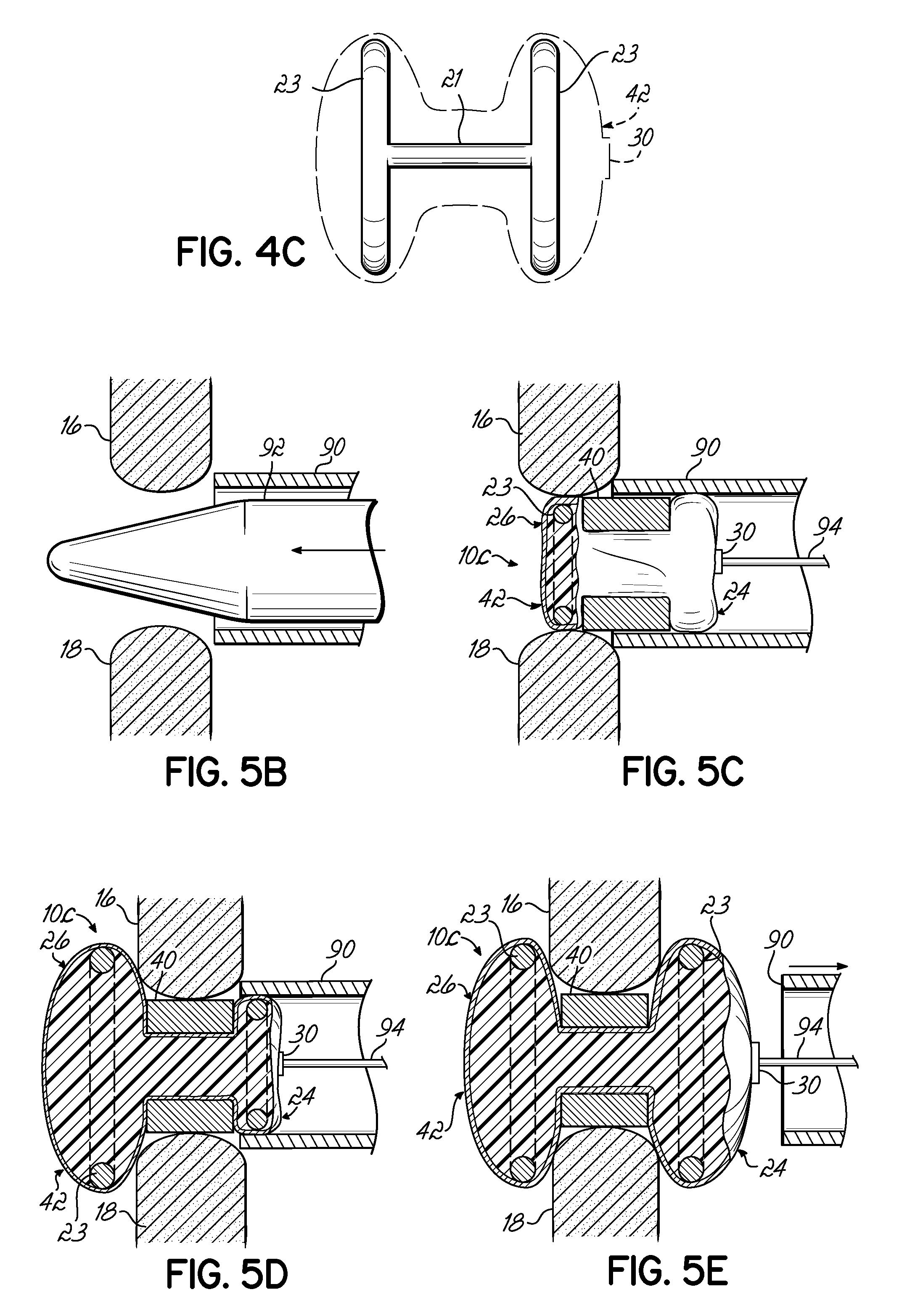
[0035]With reference to the Figures, wherein like numbers denote like parts throughout the several views, exemplary interspinous process spacers 10a-d are shown in accordance with the invention for maintaining a desired spacing between the spinous processes of adjacent vertebrae 12 and 14. According to embodiments of the invention, FIGS. 1-4 illustrate interspinous process spacers 10a-10d that possesses a geometry generally in the form of an H-shape or dumbbell (used interchangeably herein). The spacers 10a-10d comprise a medial portion 20 adapted to reside between adjacent superior spinous process 16 and the inferior spinous process 18. The medial portion 20 may comprise an expandable medial member 38 (FIGS. 2-4) and / or a rigid medial member 40 (FIGS. 1-3).

[0036]Spacers 10a-10d further comprise opposing lateral portions 24 and 26, which are located at the lateral ends of the medial portion 20. Each lateral portion 24, 26 consists of a superior lateral portion 24a, 26a adapted to re...


PUM


Abstract

An interspinous process spacer and method of implanting same is provided for maintaining separation between adjacent spinous processes of adjacent vertebrae. The spacer has two lateral portions and a medial portion therebetween, the medial portion adapted to reside between the adjacent superior and inferior spinous processes in the deployed configuration to maintain separation therebetween. The lateral portions each comprise a superior lateral portion and an inferior lateral portion adapted to reside on the lateral side of the respective superior and inferior spinous process in the deployed configuration to maintain positioning of the interspinous process spacer between the two adjacent vertebrae. The lateral portions each comprise an expandable lateral member that is expandable from an insertion configuration to the deployed configuration, and at least one of the lateral portions includes within it a lateral support member configured to be deformable for the insertion configuration and expanded in the deployed configuration. The method includes introducing the spacer through a tubular delivery device to the region between the spinous processes and positioning therein, followed by retraction of the delivery device and expansion of the expandable lateral members and lateral support members.

Description

FIELD OF THE INVENTION[0001]The present invention relates generally to devices for treating spinal stenosis, and more particularly to interspinous process spacers that can be implanted in a minimally invasive manner to treat spinal stenosis.BACKGROUND OF THE INVENTION[0002]A large majority of the population will experience back pain at some point in their lives that results from a spinal condition. The pain may range from general discomfort to disabling pain that immobilizes the individual. One type of adverse spinal condition is spinal stenosis, which occurs when the spinal canal or nerve root canals become too narrow and reduce the space for the passage of blood vessels and nerves.[0003]Lumbar spinal stenosis (“LSS”, and sometimes called sciatica) is a condition of the spine characterized by a narrowing of the lumbar spinal canal. With lumbar spinal stenosis, the spinal canal narrows and pinches the spinal cord and nerves, causing pain in the back and legs. It is estimated that ap...

Claims


Application Information

Patent Timeline
Patent Type & Authority Applications(United States)
IPC IPC(8): A61B17/70A61F2/44
CPCA61B2017/00557A61B17/7065
Inventor MORANCY-MEISTER, ANNE CATHERINEEGLI, THOMASTHOMPSON, ROSEMARYGRONAU, NICOLEGROSS, WALTERMOTZKO, MICHAELBERNHARDSGRUTTER, FABIOREINMUTH, JOCHEN
Owner ZIMMER GMBH
Why Eureka
Try Eureka