Rotor blade for a high speed rotary-wing aircraft

a rotary-wing aircraft and rotor blade technology, which is applied in the direction of marine propulsion, vessel construction, other chemical processes, etc., can solve the problems of blade approaching a stall, slow airflow velocity across the retreating blade, and the tendency of the retreating blade to stall at high forward airspeed, so as to reduce the drag of the retreating side blade, the effect of optimizing rotor performance and high-speed flight efficiency

Active Publication Date: 2007-08-07
SIKORSKY AIRCRAFT CORP
View PDF14 Cites 38 Cited by
  • Summary
  • Abstract
  • Description
  • Claims
  • Application Information

AI Technical Summary

Benefits of technology

[0009]A main rotor blade according to the present invention includes several geometric characteristics, including blade planform (chord), thickness, airfoil and twist distributions. The design is an outcome of optimizing rotor performance and high-speed flight efficiency, while satisfying structural and aeroelastic requirements throughout an anticipated flight envelope of a high speed rotary-wing aircraft. The main considerations of the blade design are: a) minimizing advancing side compressibility effects (drag), b) reducing retreating side blade drag, c) designing the rotor with sufficient blade area (solidity), d) maintaining blade aeroelastic stability and, e) maintaining blade tip separations between the upper and lower rotors.
[0010]Advancing side compressibility effects are minimized through the selection of airfoils, thickness distribution, twist, blade sweep and rotor speed scheduling with flight velocity. Retreating side blade drag in reversed flow is minimized by the redistribution of blade chord from inboard regions to outer spanwise locations, twist tailoring and incorporating particular airfoils designed to minimize drag under reversed flow conditions. Blade area (rotor solidity) maximizes operating design point performance efficiency while maintaining sufficient maneuver margin. The design parameters are defined to ensure that blade aeroelastic and tip clearance requirements are satisfied as ascertained from independent structural-dynamic and aeroelastic analyses, along with bearing design manufacturing considerations.
[0011]The main rotor blade of the present invention exhibits a unique planform shape in which the blade chord increases from the root end of the blade inboard region to the outer main region of the blade. The chord achieves a maximum dimension at a spanwise location within the main region, and then decreases toward the distal tip end. The chord distribution of the blade is one in which the chord increases smoothly from the root region to the maximum chord location within the main region following a continuous curve. The main region of the blade is also a smooth curve which tapers smoothly down to the tip chord.
[0012]Another characteristic feature of the rotor blade design is the location of the blade-feathering axis in which the feathering axis is located at a mid chord position over some inboard length of the rotor blade then transitions to a quarter chord location. The mid chord location within the root region and inboard regions of the rotor blade facilitates blade structural property distributions and manufacturing design considerations.

Problems solved by technology

Among these is the tendency of the retreating blade to stall at high forward airspeeds.
As the forward airspeed increases, the airflow velocity across the retreating blade slows such that the blade may approach a stall condition.
This dissymmetry may create an unstable condition if lift is not equalized across the advancing and retreating sides of the rotor.
The ability to off-load the retreating blades from producing lift alleviates retreating blade stall—a primary cause of speed limitation on conventional rotary wing aircraft—thereby permitting much greater forward flight speeds to be achieved.
Without rotor RPM scheduling in which rotor tip speed is reduced with increasing flight velocity, the advancing side rotor blade tips may exceed sonic velocities.

Method used


Image

  • Rotor blade for a high speed rotary-wing aircraft
  • Rotor blade for a high speed rotary-wing aircraft
  • Rotor blade for a high speed rotary-wing aircraft

Examples


Embodiment Construction

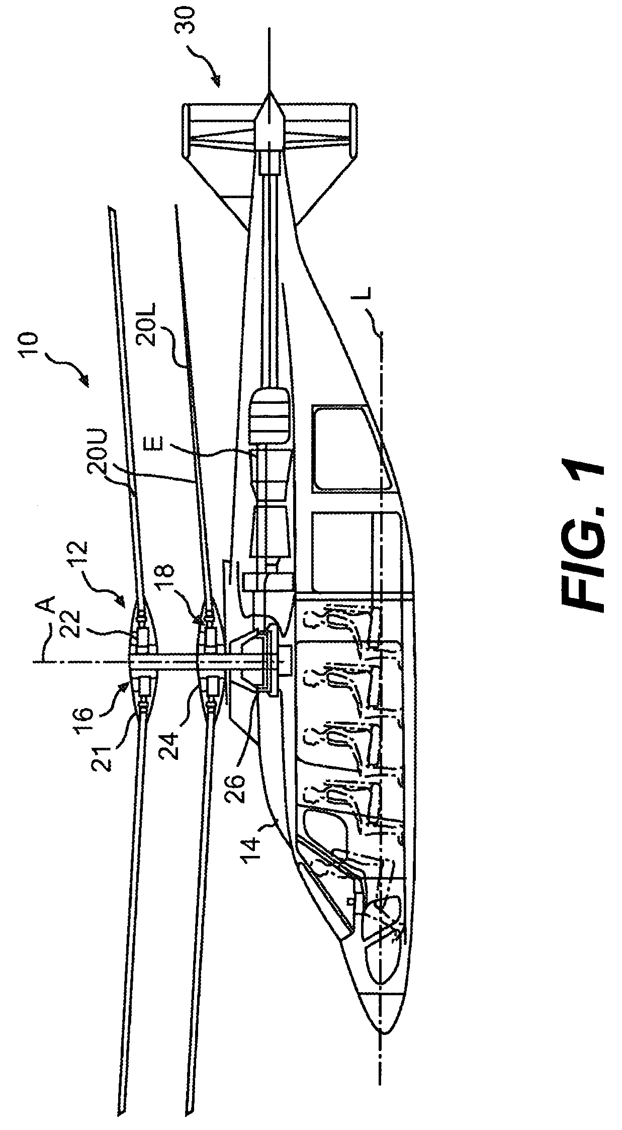
[0030]FIG. 1 illustrates an exemplary vertical takeoff and landing (VTOL) high speed compound rotary-wing aircraft 10 having a dual, contra-rotating, coaxial rotor system. 12. The aircraft 10 includes an airframe 14 that supports the rotor system 12 as well as a propulsive system 30 which provides translational thrust generally parallel to an aircraft longitudinal axis L. Although a particular aircraft configuration is illustrated in the disclosed embodiment, other machines such as single rotor helicopters, turbo-props, tilt-rotor and tilt-wing aircraft will also benefit from the present invention.

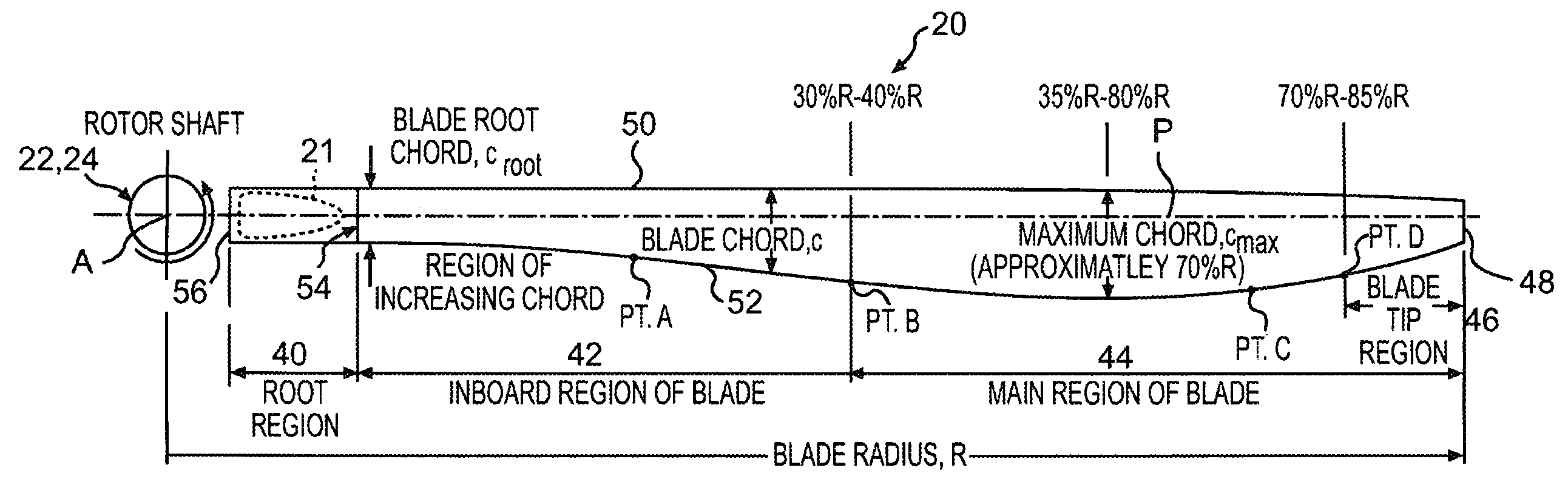
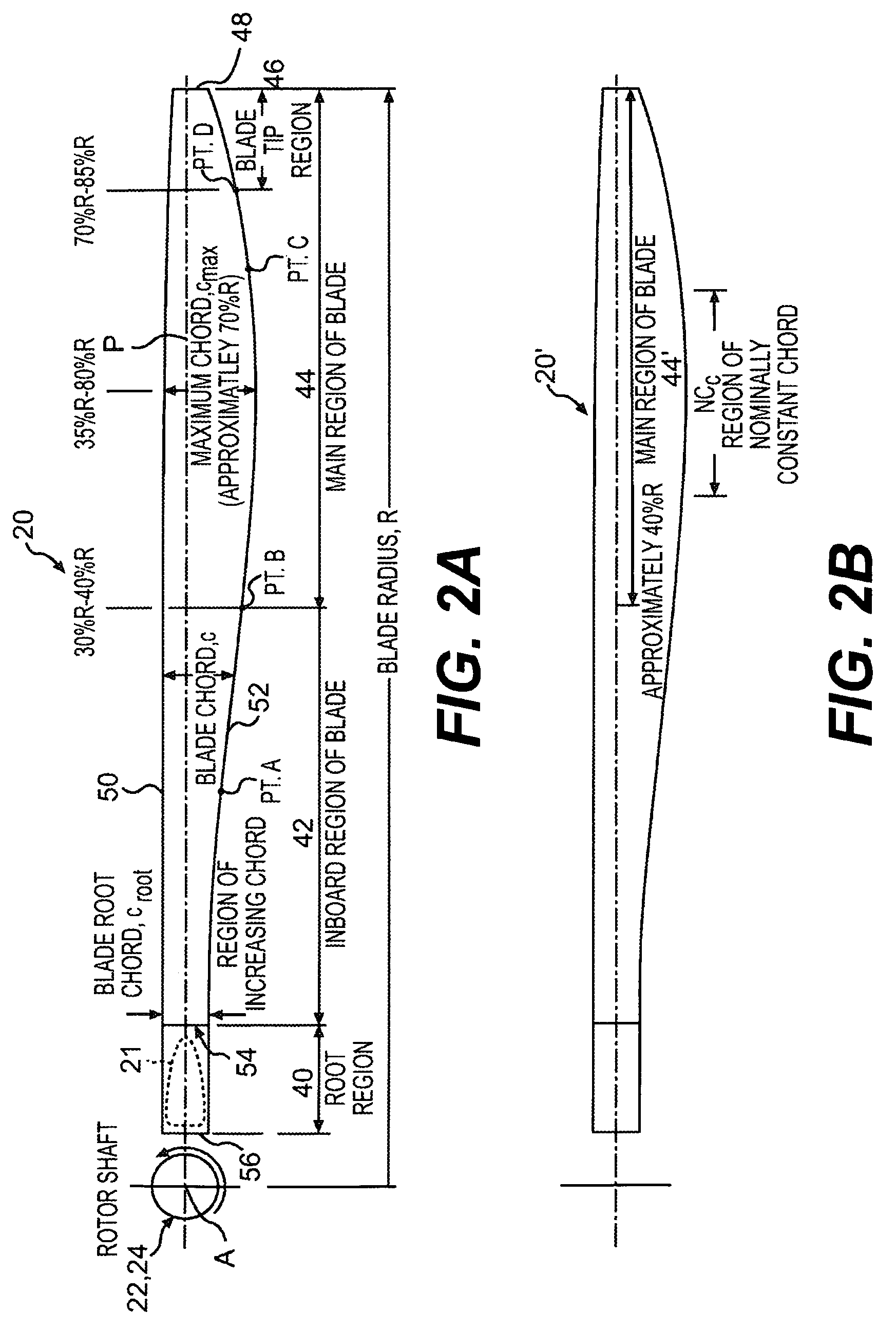
[0031]The rotor system 12 includes a first rotor system 16 and a second rotor system 18. Each rotor system 16 and 18 includes a plurality of rotor blades 20 mounted to a rotor hub assembly 22, 24 for rotation about a rotor axis of rotation A. The plurality of the main rotor blades 20 project substantially radially outward from each of the hub assemblies 22, 24 and are supported therefrom i...


PUM


Abstract

A main rotor blade exhibiting a unique planform shape in which the blade chord increases from the root end of the blade inboard region to the outer main region of the blade, where the blade chord achieves a maximum chord at a spanwise location within the main region, then decreases toward a distal tip end. The leading edge preferably is generally straight while the trailing edge is contoured to define the chord. Another characteristic feature of the rotor blade design is the location of the blade-feathering axis in which the feathering axis is located at a mid chord position over some inboard length of the rotor blade then transitions to a quarter chord location. Another characteristic feature is an airfoil distribution along the blade span that transitions from a blunt trailing edge to a sharp trailing edge airfoil suited for mid-range Mach number operation. The tip region preferably utilizes a transonic flow airfoil. Another characteristic feature of the rotor blade design is an unconventional combination of positive and negative twist gradients.

Description

BACKGROUND OF THE INVENTION[0001]The present invention is directed to a main rotor blade for rotary-wing aircraft and more particularly to a main rotor blade for a rigid coaxial, contra-rotating rotary-wing aircraft capable of hovering and cruising at speeds in excess of 250 kts.[0002]Conventional rotary-wing aircraft have a forward airspeed limited by a number of factors. Among these is the tendency of the retreating blade to stall at high forward airspeeds. As the forward airspeed increases, the airflow velocity across the retreating blade slows such that the blade may approach a stall condition. In contrast, the airflow velocity across the advancing blade increases with increasing forward speed. Forward movement of the helicopter thereby generates a dissymmetry of lift between the advancing and retreating sides of the rotor. This dissymmetry may create an unstable condition if lift is not equalized across the advancing and retreating sides of the rotor.[0003]A rotary wing aircraf...

Claims


Application Information

Patent Timeline
Patent Type & Authority Patents(United States)
IPC IPC(8): B64C27/46
CPCB64C27/10B64C27/467B64C27/82Y10S416/05B64C2027/8236Y10S416/02
Inventor BAGAI, ASHISHMOFFITT, ROBERT C.BLACKWELL, JR., ROBERT H.KRAUSS, TIMOTHY A.
Owner SIKORSKY AIRCRAFT CORP
Why Eureka
Try Eureka